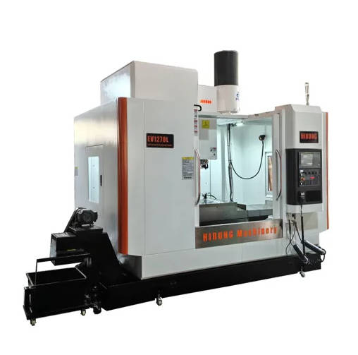
A Vertical Machining Center (VMC) is a type of computer numerical control (CNC) machine tool where the main cutting spindle is oriented vertically. This configuration is ideal for creating precise 2.5D or 3D parts by selectively removing material from a stationary workpiece mounted on a table below. VMCs are celebrated for their versatility, ease of use, and cost-effectiveness, making them a cornerstone of modern manufacturing for industries ranging from aerospace to medical device production.
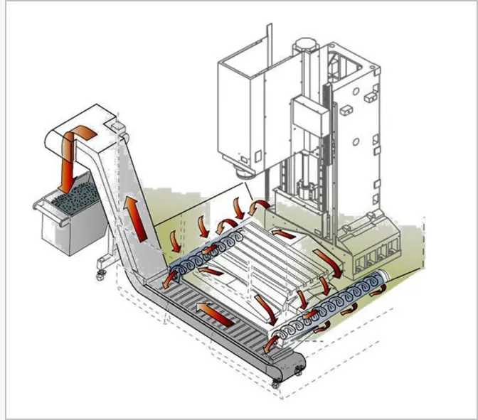
Table of Contents
- What is a Vertical Machining Center (VMC)?
- How Does a Vertical Machining Center Work? The Step-by-Step Process
- Deconstructing the Machine: Key Components of a VMC
- Exploring the Different Types of VMCs: Understanding the Axes
- VMC vs. HMC: Which is the Right Choice?
- What are the Primary Applications of a Vertical Machining Center?
- Conclusion: The Enduring Importance of the VMC
- Frequently Asked Questions (FAQ)
What is a Vertical Machining Center (VMC)?
At its core, a Vertical Machining Center is a sophisticated evolution of the traditional milling machine, automated and controlled by a computer. The defining characteristic, as the name suggests, is its vertically oriented spindle. This spindle holds and rotates the cutting tool (like an end mill or drill bit) and moves up and down along the Z-axis. The workpiece is securely clamped onto a worktable that moves horizontally along the X and Y axes. By coordinating the movement of these three primary axes, the VMC can perform a vast array of operations, including milling, drilling, tapping, and boring, to sculpt a block of raw material into a finished, high-precision component.
The term “machining center” differentiates it from a simple “milling machine” due to its inclusion of an automatic tool changer (ATC). This feature allows the machine to autonomously swap cutting tools during a program without operator intervention. This automation dramatically increases efficiency, reduces cycle times, and enables the creation of complex parts that require multiple different tools in a single setup. Because the operator can easily see and access the workpiece from the front, VMCs are exceptionally user-friendly, making them perfect for training, prototyping, and small-to-medium production runs.
How Does a Vertical Machining Center Work? The Step-by-Step Process
The operation of a VMC is a seamless integration of digital design, computer programming, and mechanical precision. The process transforms a conceptual design into a tangible, physical part through a series of carefully orchestrated steps. Understanding this workflow is key to appreciating the power and efficiency of CNC technology.
First, the journey begins with a digital design, typically created using Computer-Aided Design (CAD) software. This 3D model is then imported into Computer-Aided Manufacturing (CAM) software. A programmer or machinist uses the CAM software to define the machining strategy, selecting the appropriate cutting tools, setting speeds and feed rates, and generating the toolpaths—the exact routes the cutting tool will follow. The CAM software then translates these instructions into a specific programming language, most commonly G-code, which the VMC’s controller can understand.
Next, the G-code program is loaded into the VMC’s CNC controller. An operator prepares the machine by securely clamping a block of raw material (the workpiece) onto the worktable and loading the necessary cutting tools into the automatic tool changer’s magazine. After performing safety checks and setting the work offset (telling the machine where the part is located), the operator initiates the program. The CNC controller reads the G-code line by line, commanding the high-precision motors and drives to move the spindle and table along the X, Y, and Z axes. The VMC executes the program, automatically changing tools as required, and precisely removes material to create the final part with tolerances often measured in microns.
Deconstructing the Machine: Key Components of a VMC
A Vertical Machining Center is a complex assembly of synergistic components, each playing a critical role in its overall performance, accuracy, and reliability. From the powerful spindle to the intelligent controller, understanding these core elements provides insight into how a VMC achieves such remarkable precision.
The Spindle: The Heart of the Operation
The spindle is arguably the most vital component of a VMC. It is a precision-engineered shaft that holds the tool holder and cutting tool. Driven by a powerful motor, it provides the rotational motion (RPM) necessary for the cutting tool to shear material from the workpiece. The quality of the spindle directly impacts the machine’s surface finish capabilities, material removal rates, and overall accuracy. Spindles are categorized by their taper type (like CAT, BT, or HSK), which defines how the tool holder is held, and their maximum rotational speed, which can range from a few thousand RPM for heavy-duty cutting to over 40,000 RPM for high-speed machining of materials like aluminum.
The Worktable (or Bed): The Foundation for Precision
The worktable, or machine bed, is where the workpiece is mounted using clamps, vises, or custom fixtures. This heavy, rigid platform moves along the X and Y axes, positioning the workpiece under the spindle. The table’s surface typically features T-slots that allow for flexible and secure workholding. The size and load capacity of the worktable are primary specifications of a VMC, as they determine the maximum dimensions and weight of the part that can be machined. A flat, stable, and rigid worktable is essential for maintaining accuracy throughout the machining process, as any vibration or flex can be transferred to the finished part.
The Automatic Tool Changer (ATC): The Key to Efficiency
The Automatic Tool Changer is the defining feature that elevates a mill to a “machining center.” The ATC consists of a tool magazine (which stores a collection of tools) and a mechanical arm that rapidly swaps the tool in the spindle with the next one required by the program. Tool magazines can be drum-style or chain-style and can hold anywhere from 10 to over 100 tools. The ATC’s speed and reliability are crucial for production efficiency, as it eliminates the need for manual tool changes, enabling “lights-out” manufacturing and reducing the potential for human error.
The CNC Controller: The Brain of the VMC
The CNC (Computer Numerical Control) controller is the electronic brain of the VMC. It is a dedicated computer that reads the G-code program and translates its commands into electrical signals that direct the machine’s motors, drives, and other systems. The controller manages the precise positioning of the axes, controls the spindle speed, activates the coolant systems, and orchestrates the tool changes. Modern controllers from manufacturers like Fanuc, Siemens, and Haas feature user-friendly interfaces with graphical displays, making it easier for operators to set up jobs, monitor progress, and troubleshoot issues.
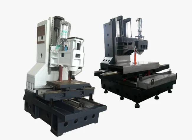
The Machine Structure: Frame, Column, and Enclosure
The overall structure of a VMC—comprising the base, column, and frame—is engineered for maximum rigidity and vibration damping. Most high-quality VMCs are built with a cast iron frame, which is excellent at absorbing vibrations generated during heavy cutting. The massive column supports the spindle assembly (the “headstock”) and guides its vertical movement along the Z-axis. The entire work area is contained within a full enclosure, which serves multiple purposes: it protects the operator from flying chips and cutting fluid, contains the coolant for recycling, and helps to muffle operational noise.
Coolant and Chip Management Systems
Machining generates a significant amount of heat and sharp metal chips. Coolant and chip management systems are essential for maintaining tool life, achieving good surface finishes, and ensuring reliable operation. The coolant system pumps a mixture of water and lubricant (coolant) directly to the cutting zone. This fluid cools the tool and workpiece, lubricates the cutting action, and flushes chips away. The chips and used coolant fall to the bottom of the enclosure, where a chip conveyor or auger system transports the solid waste into a bin for disposal, while the coolant is filtered and recirculated.
Exploring the Different Types of VMCs: Understanding the Axes
While all VMCs share a vertical spindle orientation, they are primarily categorized by the number of axes of motion they can control. This number determines the complexity of the parts the machine can produce in a single setup. The three main types are 3-axis, 4-axis, and 5-axis machines.
The Standard Workhorse: 3-Axis VMCs
A 3-axis VMC is the most common and fundamental type. It operates on the three linear axes: X (left-right), Y (front-back), and Z (up-down). In this setup, the cutting tool moves along the Z-axis while the worktable moves along the X and Y axes. 3-axis machining is perfect for producing parts with flat surfaces, pockets, holes, and profiles, often referred to as 2.5D parts. It is relatively simple to program and operate, making it an incredibly versatile and cost-effective solution for a wide range of applications.
Adding a Dimension: 4-Axis VMCs
A 4-axis VMC builds upon the standard 3-axis setup by adding a rotational axis, typically designated as the A-axis. This is usually achieved by mounting a rotary table or indexer onto the main worktable. This A-axis rotates the workpiece, allowing the cutting tool to access four sides of the part without requiring a new setup. This capability is invaluable for machining features on cylindrical parts or for drilling holes on multiple faces of a block, significantly reducing setup time and improving accuracy by minimizing part handling.
The Apex of Complexity: 5-Axis VMCs
A 5-axis VMC provides the ultimate level of machining capability by adding two rotational axes to the three linear axes. These can be configured in various ways, such as a tilting spindle and a rotating table (trunnion style) or a two-axis rotating table. With 5-axis simultaneous machining, the machine can move all five axes at the same time, enabling it to produce incredibly complex shapes, contoured surfaces, and deep undercuts in a single clamping. This is essential for manufacturing parts like turbine blades, impellers, and complex medical implants, where supreme accuracy and surface finish are required.
| Feature | 3-Axis VMC | 4-Axis VMC | 5-Axis VMC |
|---|---|---|---|
| Axes of Motion | X, Y, Z (Linear) | X, Y, Z + A (Rotation) | X, Y, Z + A & B (or C) (Two Rotational) |
| Part Complexity | Low to Medium (2.5D parts) | Medium (Multi-sided parts) | High (Complex contours, undercuts) |
| Ideal For | Plates, brackets, simple molds | Cylindrical parts, parts needing side-work | Aerospace components, impellers, medical implants |
| Cost & Programming | Lowest cost, simplest programming | Moderate cost and complexity | Highest cost, most complex programming |
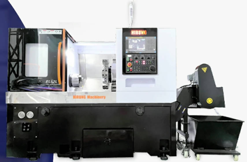
VMC vs. HMC: Which is the Right Choice?
When considering a machining center, the most fundamental choice is between a Vertical Machining Center (VMC) and a Horizontal Machining Center (HMC). The primary difference is the spindle orientation. While a VMC’s spindle is vertical, an HMC’s spindle is horizontal. This single design difference leads to significant variations in capability, cost, and ideal use cases. Choosing the right machine depends entirely on the specific application, production volume, and part geometry.
A VMC is often the preferred choice for several reasons. Its main advantage is visibility and accessibility. The operator can easily see the cutting process, which simplifies setup, monitoring, and manual adjustments. VMCs typically have a smaller footprint and are significantly less expensive than their horizontal counterparts, making them an excellent entry point for smaller shops or for prototyping work. They excel at “one-and-done” jobs or work on flat, plate-like parts where most of the features are on a single face. However, their main limitation is chip evacuation. Gravity causes chips to pile up on the workpiece, which can lead to recutting chips and poor surface finishes if not managed properly with high-pressure coolant.
An HMC, on the other hand, excels where a VMC struggles. With its horizontal spindle, gravity works as an advantage, allowing chips to fall away from the workpiece and into the chip conveyor below. This results in better tool life and superior surface finishes, especially in deep pockets. HMCs are often equipped with a two-pallet system, which allows an operator to set up a new part on one pallet while the machine is working on another, drastically reducing downtime and boosting productivity. This makes them ideal for high-volume production. Their main drawbacks are their higher initial cost, larger footprint, and the reduced visibility of the cutting zone, which can make setups more challenging.
| Aspect | Vertical Machining Center (VMC) | Horizontal Machining Center (HMC) |
|---|---|---|
| Spindle Orientation | Vertical (Up/Down) | Horizontal (Side-to-Side) |
| Chip Evacuation | Poor (Gravity works against it) | Excellent (Gravity aids chip removal) |
| Ideal Workpiece | Flat parts, single-setup jobs, die/mold work | Cubic parts, multi-sided parts, high-volume production |
| Cost | Lower | Higher |
| Productivity | Good for small to medium runs | Excellent for high-volume runs (with pallet changers) |
| Visibility & Setup | Excellent visibility, easy setup | Limited visibility, more complex setup |
What are the Primary Applications of a Vertical Machining Center?
The versatility and precision of VMCs have made them indispensable across a multitude of industries. Their ability to efficiently machine a wide range of materials into complex shapes means they are found in nearly every sector of modern manufacturing. From creating critical aerospace components to crafting delicate medical instruments, the VMC is a true industrial workhorse.
Key industries that rely heavily on VMCs include:
- Aerospace: For manufacturing structural components, brackets, and fittings from aluminum and titanium alloys where high precision and strength-to-weight ratios are critical.
- Automotive: Used for prototyping new engine parts, creating molds for plastic components, and machining custom performance parts.
- Medical: For producing highly precise surgical instruments, orthopedic implants, and custom prosthetics from materials like stainless steel and titanium.
- Mold & Die Making: VMCs are the go-to machine for creating injection molds, stamping dies, and casting patterns due to their ability to produce fine details and excellent surface finishes.
- General Job Shops: These are the backbone of the manufacturing industry, using VMCs to produce a vast variety of custom parts for countless different clients and applications.
VMCs are capable of machining a broad spectrum of materials, including various grades of steel, aluminum, stainless steel, titanium, brass, copper, and many types of plastics and composites. The choice of material dictates the required spindle speed, feed rates, and cutting tools for a successful machining operation.
Conclusion: The Enduring Importance of the VMC
The Vertical Machining Center is more than just a machine; it is a foundational pillar of modern manufacturing. Its elegant combination of a vertically oriented spindle, automated tool changing, and precise computer control provides an accessible, versatile, and powerful solution for part production. From the simplest 3-axis machine in a small job shop to a complex 5-axis system in a high-tech aerospace facility, the VMC continues to be the workhorse of choice for countless applications. Understanding its fundamental components, operational principles, and different configurations is the first step toward harnessing its full potential to turn digital ideas into physical reality.
Frequently Asked Questions (FAQ)
What is the main difference between a VMC and a CNC milling machine?
While the terms are often used interchangeably, a “machining center” (like a VMC) specifically includes an automatic tool changer (ATC). A basic CNC milling machine may not have an ATC, requiring the operator to manually change tools. All VMCs are CNC milling machines, but not all CNC milling machines are VMCs.
How much does a VMC cost?
The cost of a VMC varies dramatically based on its size, number of axes, spindle speed, brand, and features. A small, entry-level 3-axis VMC might cost between $40,000 and $80,000, while a large, high-speed 5-axis machine from a premium brand can easily exceed $500,000.
What programming language do VMCs use?
The vast majority of VMCs are programmed using a language called G-code (also known as RS-274). G-code is a set of instructions that tell the machine where to move, how fast to move, and what actions to perform. While it can be written by hand, it is most often generated automatically by CAM (Computer-Aided Manufacturing) software.