
5 Axis Gantry Universal Machining Center
GU Series
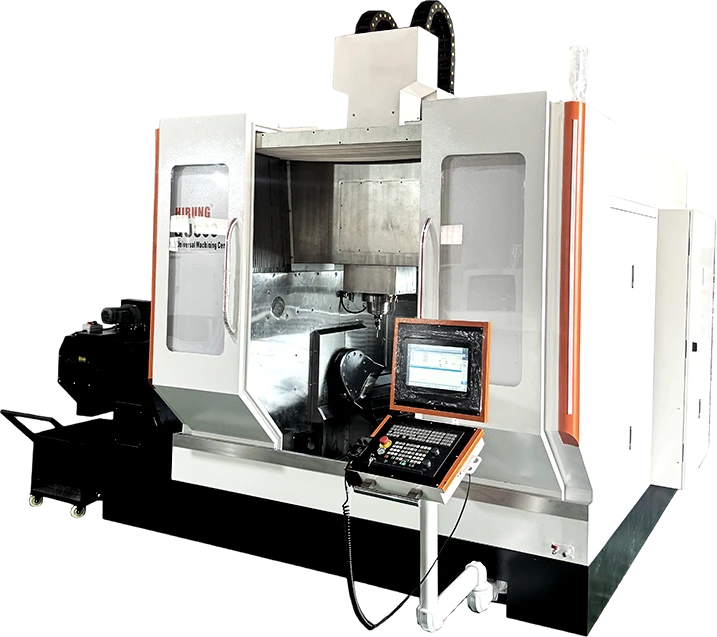
The HIRUNG GU Series is a high-rigidity 5 axis gantry universal machining center designed for complex parts that require multi-surface machining, accurate rotary-axis positioning and fewer workpiece setups.
Its gantry-type linear-axis structure works together with a direct-drive B/C rotary table, allowing the cutting tool to approach the workpiece from multiple directions. The series includes multiple machine sizes to accommodate different workpiece dimensions, fixture weights and machining requirements.
The GU Series is suitable for manufacturers producing complex precision components for aerospace, medical equipment, precision engineering and other demanding industrial applications.

5 AXIS GANTRY UNIVERSAL MACINNING CENTER
Best Machine to improve processing accuracy &efficiency
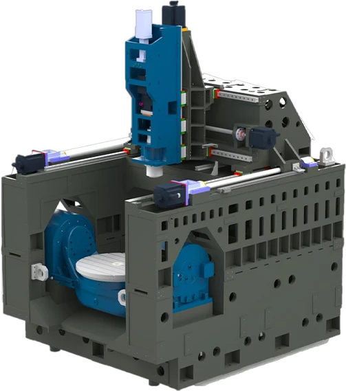
GU series have delicate and compact,high rigidity machine casting body structure,showing the unique machine rigidity and stability.Machine casting body adopt Germany Meehannite,Tempering treatment,Stress treatment to make sure the machine casting body no deformation. Besides the machine have high rapid feedrate ,it also have low rictional resistance and high positioning accuracy,gantry column type 3 axis moving structure will highly avoid the malfunction when procesing if leakage of cutting fluid ,to make sure the machine high stability.
- CNC gantry structure, with stronger X/Y/Z rigidity and higher precision;
- The 5-axis rotary table adopts a DD double support design, with strong load-bearing capacity, higher precision, and faster response speed;
- The spindle adopts an HSKA63 built-in electric spindle, with selectable speeds of 18,000 and 24,000 rpm;
A 5 Axis Machining Platform for Complex Precision Parts
Complex components often include inclined holes, curved surfaces, deep cavities, compound angles and features located on several sides of the workpiece.
When these parts are produced on a conventional three-axis machining center, several fixtures and repeated workpiece repositioning may be required. Each additional setup increases handling time and may introduce another source of datum or positioning variation.
The GU Series combines three linear axes with a tilting and rotating worktable. This configuration allows more surfaces to be machined in one setup, helping manufacturers reduce repeated clamping and maintain more consistent positional relationships between machined features.
Depending on the selected CNC system, programming method and machine configuration, the GU Series can support indexed multi-sided machining and simultaneous five-axis machining applications.
Reduce Setups Without Compromising Machining Access
The main value of a five-axis machining center is not simply the number of controlled axes. It is the ability to complete more machining operations without repeatedly removing and repositioning the workpiece.
For suitable components, the GU Series can help:
- Reduce repeated workpiece alignment
- Reach inclined and multi-directional features
- Maintain consistent datum relationships
- Improve access to complex surfaces and cavities
- Reduce dependence on multiple dedicated fixtures
- Consolidate roughing, drilling and finishing operations
- Shorten non-cutting setup time
Actual productivity improvements depend on the part geometry, toolpath, fixture design, CNC system and machining process.
High-Rigidity Gantry Structure
The GU Series uses a gantry-type structure to provide a stable mechanical foundation for multi-axis machining.
During five-axis movement, the spindle and rotary axes may change direction frequently. The machine structure must therefore resist changing cutting forces while maintaining stable geometric relationships between the spindle, linear axes and rotary table
The rigid gantry layout helps support:
- Stable linear-axis movement
- Controlled vibration during cutting
- Consistent positioning under changing loads
- Precision contour machining
- Long machining cycles
- Roughing and finishing on the same platform
The machine structure is designed to balance rigidity, dynamic response and machining accessibility rather than relying only on high spindle speed.
Stabilized Machine Body for Long-Term Accuracy
The machine body provides the dimensional foundation for every moving component.
HIRUNG uses stabilized structural components designed to reduce the effect of internal stress on machine geometry. Precision machining and controlled assembly help maintain the relative position of the gantry, linear guideways, spindle and rotary table.
A stable machine body is particularly important for parts requiring:
- Accurate feature positioning
- Consistent surface quality
- Long continuous machining cycles
- Multi-directional machining
- Repeated production over extended periods
Machine accuracy must still be evaluated together with installation conditions, machine leveling, temperature control, tooling, fixtures and the machining process.
Direct-Drive B/C Rotary Table
The B/C rotary table controls the angular position of the workpiece and is one of the most important systems in a five-axis machining center.
The GU Series uses direct-drive technology to transmit motor motion directly to the rotary axes. Compared with a conventional transmission mechanism containing more intermediate components, direct drive can provide faster response and more direct angular positioning.
The rotary table helps the machine reach:
- Inclined faces
- Side features
- Compound-angle holes
- Complex profiles
- Multi-directional cavities
- Features distributed around the workpiece
The double-supported table structure is designed to provide stable support during workpiece rotation and tilting.
Rotary-axis capacity, table load and working range vary by GU model. Please refer to the original Machine Parameters table for detailed specifications.
High-Speed Spindle for Flexible Machining Requirements
The spindle determines how effectively the machine can match different materials, cutting tools and machining processes.
The GU Series provides spindle configurations intended to balance speed, rigidity and machining stability. Depending on the selected model and configuration, the machine can be adapted for precision finishing, contour machining, drilling and controlled material removal.
The spindle system is designed to support:
- Stable tool clamping
- High-speed machining
- Controlled thermal behavior
- Repeatable tool positioning
- Precision surface finishing
- Machining with different tool lengths and diameters
Spindle speed alone should not determine machine selection. Workpiece material, tool diameter, cutting depth, torque requirement and production cycle must also be considered.
Detailed spindle specifications remain in the original Machine Parameters table.
Thermal Control for More Stable Machining
Spindle temperature changes can affect machining consistency during extended production cycles.
The spindle cooling system helps control heat generated during continuous spindle operation. Reducing uncontrolled temperature variation can support more stable spindle behavior and help limit the effect of thermal expansion on precision machining.
Thermal stability also depends on:
- Workshop temperature
- Machine warm-up procedure
- Cutting conditions
- Coolant temperature
- Machining-cycle duration
- Machine installation environment
For parts with demanding tolerance requirements, the complete thermal condition should be considered during process planning and machine acceptance.
Precision Linear Motion System
The X, Y and Z axes are responsible for positioning the spindle relative to the workpiece.
The GU Series uses a linear motion system designed to provide stable feed movement during rapid positioning, contour machining and precision finishing.
The linear-axis design helps support:
- Responsive axis acceleration and deceleration
- Smooth movement during contour machining
- Stable positioning under changing cutting loads
- Consistent low-speed feed
- Efficient movement between machining positions
- Reliable performance during repeated production
The final machining result depends on the complete system, including servo control, ball screws, guideways, feedback devices, machine calibration and CNC parameter settings.
Roller Linear Guideways for Rigidity and Motion Stability
Roller linear guideways provide a large contact area between the moving and supporting components.
This structure helps the linear axes maintain rigidity while supporting rapid motion and controlled low-speed feed. It is especially valuable when machining conditions change repeatedly during multi-axis toolpaths.
The guideway system is selected to balance:
- Load capacity
- Motion response
- Structural rigidity
- Feed stability
- Positioning repeatability
- Resistance to changing cutting forces
Proper lubrication and routine maintenance are essential for maintaining long-term guideway performance.
Direct-Connected Ball Screw Drive
The linear axes use direct-connected drive systems to transmit servo-motor motion to the ball screws.
Reducing unnecessary transmission interfaces helps create a more direct drive path between the motor and moving axis. This supports responsive positioning and consistent feed movement.
The ball screw system works together with the servo motors, guideways and CNC controller. It should not be evaluated as an isolated component.
Detailed axis travel and feed specifications remain in the original Machine Parameters table.
Position Feedback for Demanding Accuracy Requirements
Position feedback systems help the CNC controller monitor the actual movement of the machine axes.
Depending on the machine configuration, additional feedback devices can be selected for applications requiring tighter control of positioning variation.
These options may be considered for:
- Precision finishing
- Long machining cycles
- Tight positional tolerances
- Complex multi-axis contours
- Components with critical feature relationships
- Production environments with demanding acceptance standards
The need for additional linear-axis feedback should be evaluated according to the part tolerance, process capability and inspection method rather than selected automatically for every application.
Automatic Tool Changer for Multi-Process Machining
Complex five-axis parts often require several cutting tools within one machining cycle.
The automatic tool changer allows the machine to switch between roughing, drilling, finishing, chamfering and inspection tools without manual intervention after every process.
Tool magazine selection should consider:
- Number of tools required per part
- Tool diameter and length
- Maximum tool weight
- Redundant tools for long production cycles
- Number of part types produced
- Planned unattended machining time
Tool magazine capacity and tool limitations vary according to machine model and configuration. Please retain the existing values in the original Machine Parameters table.
Standard Equipment
The GU Series standard equipment is configured to support machine operation, spindle cooling, tool management, lubrication, chip removal and operator protection.
The exact standard configuration may vary according to the selected GU model, CNC system and destination market.
Review the following standard-equipment list together with the technical quotation. Any equipment that is essential to the customer’s machining process should be clearly confirmed before the order is finalized.
Standard Equipment
The standard-equipment list defines what is included in the base machine configuration.
Before comparing quotations from different machine suppliers, buyers should confirm whether the listed equipment includes the required:
- Tool management system
- Cooling system
- Chip-removal system
- Lubrication system
- Machine protection
- Electrical cabinet cooling
- Rotary-axis feedback
- Installation accessories
- Operation documents
A lower machine quotation may exclude equipment that must later be purchased separately. The complete configuration should therefore be compared rather than only the machine price.
Optional Equipment
Optional equipment allows the GU Series to be adapted to different materials, accuracy requirements, inspection methods and production environments.
Not every option is required for every application. Selection should be based on the actual machining process and return on investment.
Options related to measurement, position feedback, coolant pressure, chip management and five-axis calibration should be reviewed together with the part drawing and production target.
How to Select Optional Equipment
Additional position feedback may be valuable for applications with demanding positioning requirements.
Tool measurement can help reduce manual tool-setting work and identify tool-length or tool-condition issues.
Workpiece probing can support workpiece alignment, datum confirmation and in-process measurement, depending on the selected probing and software configuration.
Through-spindle coolant may be considered for deep-hole drilling, chip evacuation and machining processes that require coolant to reach the cutting edge through the tool.
Five-axis calibration equipment can assist with checking and compensating the relationship between the linear and rotary axes.
The final option package should be confirmed according to the part, material, tolerance, cycle time and operating method.
GU Series Easy for Complex Parts
The preferred choice for high-precision parts in aerospace, medical and other fields
Mechanical Structure
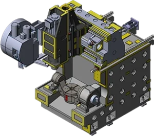
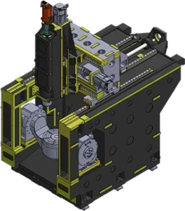
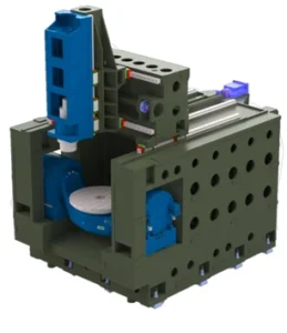
Y-Axis single drive
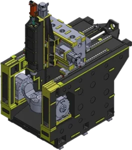
Y-axis dual drive
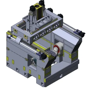
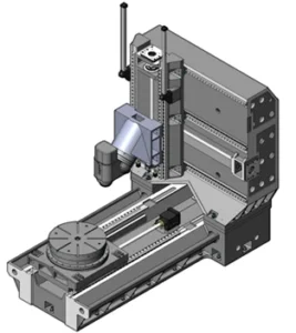
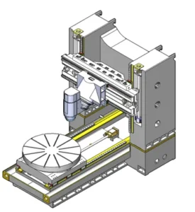
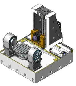

The 5-axis rotary table uses Taiwan brands HIWIN or SOLPOWER, which offer greater stability and a longer lifespan compared to other inferior brands.
Rotating slant working table:
1. B Axis slant angle: +120°~-120°
2. C Axis slant angle: 360°
3. The B/C axes are driven by built-in DD motors,which offer high speed and higher precision.
4. Rotating slant working table max load: 1200kgs(GU800)
5.Standard built-in optical scale, with an accuracy of up to 4 sec
High-precision Protection
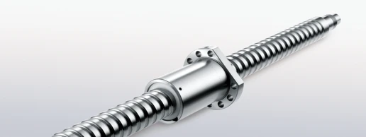
Direct Driver
3 Axis ball screw adopt direct drivers , eliminating backlash problems,to make sure the accuracy transmission characteristics.
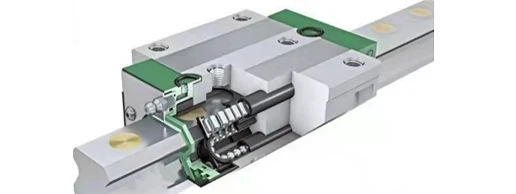
Rigid Precision Linear Roller Guides
The X/Y/Z axes use linear roller guides, which are highly rigid and precise.
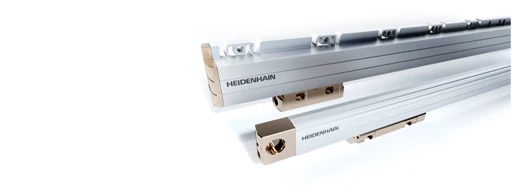
HEIDENHAIN or FAGOR 3 Axis Optical ruler (OP)
Optical scales are available as optional accessories for the X/Y/Z Axis to ensure higher precision operation of the machine tool.
Still can’t find your vertical machining center?
Contact Our Experts For A Professional & Cost-Effective Solution
Spindle
- The standard is HSK A63, which can produce stronger clamping force and improve accuracy during high-speed operation;
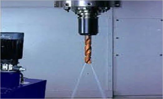
- The spindle is equipped with an oil temperature cooler as standard to avoid thermal extension caused by motor heating;
- The 30KW built-in electric spindle has high speed and can generate high torque. It is not only suitable for high-precision machining, but can also easily handle some necessary heavy cutting.


Standard Accessory
- 1. Fully enclosed guard
- 2. working light
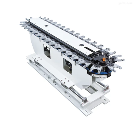
- 3. Arm type tool magazine
- 4.warning light
- 5. Spindle oil cooling
- 6.M30 Auto power off
- 7.cutting coolant system
- 8. Removable hand artery balance generator
- 9.Automatic centralized lubrication system
- 10.RS-232
- 11.B/C axis optical scale
- 12.Electrical box air conditioner
- 13.Spindle blowing device
- 14.tool box
- 15.Chip cutting device
- 16.Leveling bolts and pads
- 17.Automatic chip conveyor and chip trolley
- 18.Oil-water separator
- 19.Operation and maintenance manual
Optional Accessories
- 1. 3Axis optical ruler(HEIDENHAIN or FAGOR)
- 2.Cooling throught spinde (CTS) 24/45/70bar
- 3.Oil mist collector
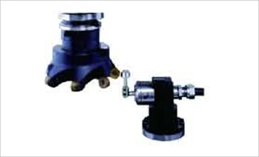
- 4.Automatic tool measuring device
- Renishaw TS27R
- BLUM -ZX speed TR
- BLUM --ZX speed RC
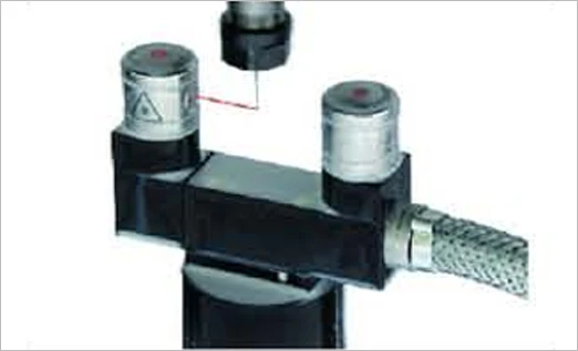
- 5.Non-contact tool measuring device
- 6.Workpiece detection device (Renishaw OMP40-2/BLUM ----TC 52)
- 7.Workpiece inspection device (Renishaw OMP400/BLUM ----TC 52)
- 8.5-axis center calibration included
Machine Parameters
The GU Series includes multiple machine sizes for different workpiece dimensions, fixture weights and machining requirements.
Use the following parameter table as an initial reference when comparing GU models. Final model selection should not be based on only one specification such as rotary-table diameter or axis travel.
Model Unite | GU260 | GU400 | GU630 | GU635 | GU800 | GU805 |
Travel | ||||||
X/Y/Z Travel mm | 500/550/450 | 500/650/450 | 700/900/500 | 750/1000/600 | 850/1000/600 | 850/1000/600 |
Ditance | ||||||
Spindle nose to working table mm | 140-590 | 100-550 | 120-620 | 150-750 | 180-780 | 180-780 |
Working Table | ||||||
Working table size mm | Φ260(320) | Φ400(500) | Φ630 | Φ630 | Φ800 | Φ800 |
Max table load kg | 120 | 200 | 850 | 850 | 1200 | 1200 |
B/C rotate angle deg | ±120°/360° | |||||
B /C axis driving method | Built-in electric spindle | |||||
B/C axis Rotation speed rpm /min | 100/150 | 100/150 | 60/100 | 60/100 | 60/90 | 60/90 |
B/C axis braking torque Nm | 500/300 | 1380/840 | 4800/2400 | 4800/2400 | 8400/4200 | 8400/4200 |
Spindle taper | ISO40 | |||||
Spindle max speed rpm | HSK A63 16000/18000 /24000(OP BT40 12000rpm BBT40 /15000rpm ) | |||||
spindel motor S1 /S3 kw | 18.5/20.3 | 30/33.3 | ||||
Spindle torque S1/S3 Nm | 47.7/57.3 | 100/120(16000rpm) 72/85(18000rpm ) 47.7/57.3(24000rpm) | ||||
Rapid feedrate | GU260 | GU400 | GU630 | GU635 | GU800 | GU805 | |
Rapid feedrate X/Y/Z Axis m/min | 36/36/36 | ||||||
Rapid feedrate mm/min | 15000 | ||||||
Tools | |||||||
Max tool No | 24/32 | 32/40 | |||||
Change way | Bidirectional arbitrary knife selection | ||||||
Max tool weight kg | 8 | ||||||
Max tool length mm | 250 | 300 | |||||
Max tool Dia mm | 75/120 | ||||||
Too change time sec | GU260 :1.5 /3.5(T to T) | ||||||
Accuracy | |||||||
positioning accuracy(X/Y/Z) mm | 0.008(VDI 3441) | ||||||
positioning accuracy(B/C) sec | 10“ | ||||||
Repeatability(X/Y/Z) mm | 0.004(VDI 3441) | ||||||
Repeatability(B/C) sec | 4” | ||||||
Others | |||||||
Floor space mm | 2600*1900 | 2884*2091 | 3450*2550 | 3450*2550 | 3600*2800 | 3600*2800 | |
Machinery Max height mm | 2800 | 2800 | 3500 | 3547 | 3547 | 3547 | |
Machine Net weight kg | 7000 | 8000 | 12000 | 15000 | 14800 | 17800 | |
Power requirements KVA | 50 | 50 | 70 | 75 | 75 | 80 | |
Control system | SIEMENS ONE 15-inch (OP:HEIDENHAIN/SYNTEC) | ||||||
Rapid feedrate | GU400A/GU400F | GU630A/800A | GU630Q/800Q | GU800B | GU1700B | GU800H |
Rapid feedrate X/Y/Z Axis m/min | F:60*60*60 | 36*36*36 | ||||
Rapid feedrate mm/min | 25000 | 15000 | ||||
Tools | ||||||
Max tool No | 24/32 | 32/40 | 32/40/60 | 32/40 | ||
Change way | Bidirectional arbitrary knife selection | |||||
Max tool weight kg | 8 | |||||
Max tool length mm | 250(GU260:200) | |||||
Max tool Dia mm | 70/110 | |||||
Too change time sec | 1.5(T to T) | 3.5(T to T) | 2.2 | 2.2 | 2.2 | |
Accuracy | ||||||
positioning accuracy(X/Y/Z) mm | 0.008(VDI 3441) | |||||
positioning accuracy(B/C) sec | 10“ | |||||
Repeatability(X/Y/Z) mm | 0.004(VDI 3441) | |||||
Repeatability(B/C) sec | 4” | |||||
Others | ||||||
Floor space mm | 2200*1800 | 3450*2550 3600*2800 | 3800*2850 4200*2980 | 4100*2985 | 6600*3900 | 6622*2600 |
Machinery Max height mm | 2800 | 3500 | 3500 | 3800 | 4200 | 3547 |
Machine Net weight kg | 8000 | 12000/15000 | 16000/18000 | 19800 | 40000 | 17800 |
Power requirements KVA | 50/F:80 | 70 | 80 | 90-120 | 100/130 | 80 |
Control system | SIEMENS ONE 15-inch (OP:HEIDENHAIN/SYNTEC) | |||||
Rapid feedrate | GU400A/GU400F | GU630A/800A | GU630Q/800Q | GU800B | GU1700B | GU800H |
Rapid feedrate X/Y/Z Axis m/min | F:60*60*60 | 36*36*36 | ||||
Rapid feedrate mm/min | 25000 | 15000 | ||||
Tools | ||||||
Max tool No | 24/32 | 32/40 | 32/40/60 | 32/40 | ||
Change way | Bidirectional arbitrary knife selection | |||||
Max tool weight kg | 8 | |||||
Max tool length mm | 250(GU260:200) | |||||
Max tool Dia mm | 70/110 | |||||
Too change time sec | 1.5(T to T) | 3.5(T to T) | 2.2 | 2.2 | 2.2 | |
Accuracy | ||||||
positioning accuracy(X/Y/Z) mm | 0.008(VDI 3441) | |||||
positioning accuracy(B/C) sec | 10“ | |||||
Repeatability(X/Y/Z) mm | 0.004(VDI 3441) | |||||
Repeatability(B/C) sec | 4” | |||||
Others | ||||||
Floor space mm | 2200*1800 | 3450*2550 3600*2800 | 3800*2850 4200*2980 | 4100*2985 | 6600*3900 | 6622*2600 |
Machinery Max height mm | 2800 | 3500 | 3500 | 3800 | 4200 | 3547 |
Machine Net weight kg | 8000 | 12000/15000 | 16000/18000 | 19800 | 40000 | 17800 |
Power requirements KVA | 50/F:80 | 70 | 80 | 90-120 | 100/130 | 80 |
Control system | SIEMENS ONE 15-inch (OP:HEIDENHAIN/SYNTEC) | |||||
How to Compare GU Series Models
A workpiece may fit within the nominal table diameter but still interfere with the spindle, machine enclosure or other components when the rotary table tilts.
For this reason, model selection must consider the complete rotating envelope rather than only the part diameter.
Workpiece and Fixture Weight
The rotary-axis load includes the workpiece, chuck, fixture, clamping plate and any supporting components.
An off-center load can also create different demands from a centrally positioned workpiece of the same total weight.
Tool Clearance
Fixture height, workpiece height, tool length and spindle approach angle affect the actual usable machining space.
A longer tool may provide access to a deep feature but can also reduce rigidity and create additional interference risk.
Spindle Requirements
High spindle speed may be more important for small tools and precision finishing, while torque and structural rigidity may be more important for larger tools and heavier material removal.
Machining Accuracy
Published positioning values are only one part of the final machining capability.
Tooling, fixtures, temperature, machine installation, programming, calibration and inspection methods also affect the finished part.
Send the part drawing and fixture information to HIRUNG before confirming the GU model.
Hear the Voices of Our Clients
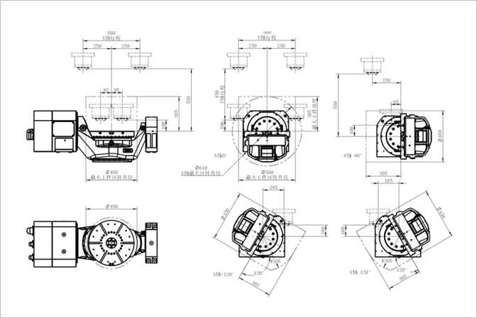
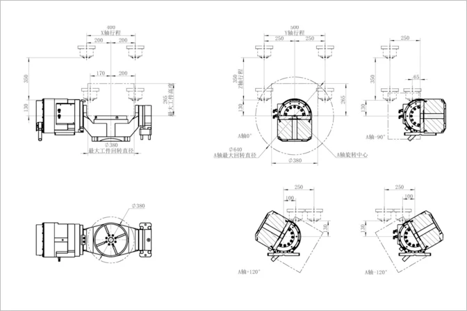
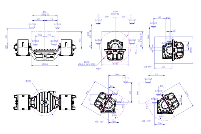
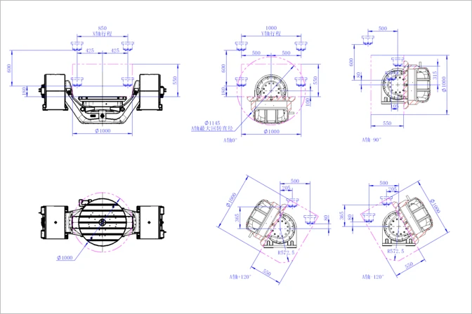
Mechanical Drawings
Review the machine dimensions before confirming factory layout, transportation and installation.
The mechanical drawings provide reference information for:
- Machine footprint
- Overall machine dimensions
- Operator access
- Maintenance space
- Chip conveyor position
- Electrical cabinet location
- Loading and unloading access
- Workshop door clearance
- Foundation and leveling preparation
The final installation drawing should be confirmed according to the selected GU model and machine configuration.
Do not design the workshop layout using only a general product-page drawing, as optional equipment may affect the final machine dimensions and installation requirements.
Applications of the GU Series
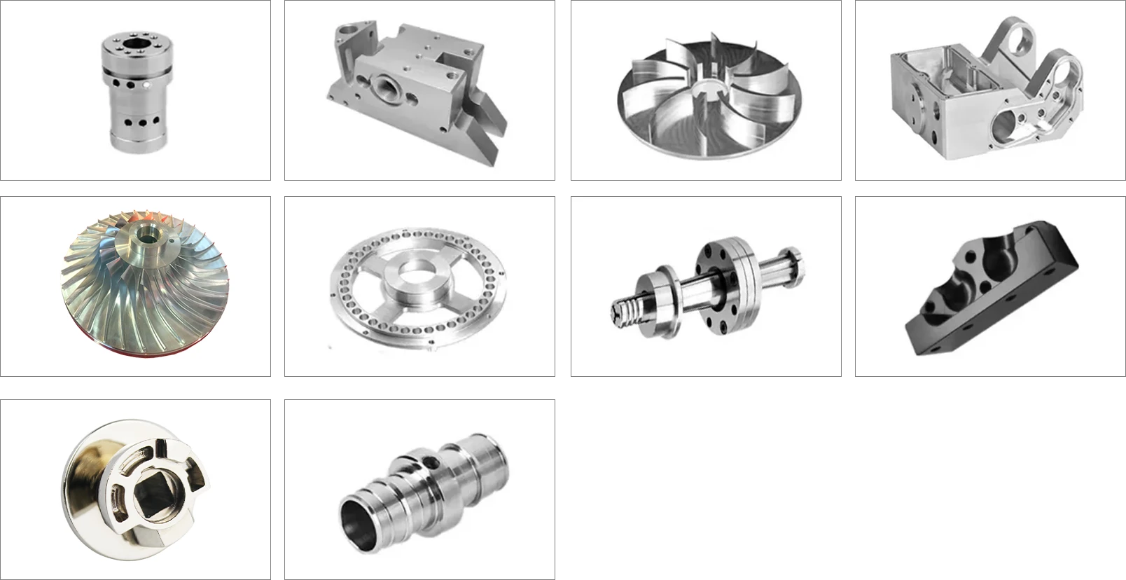
The GU Series is intended for complex components that require machining from multiple directions, stable feature relationships and reduced workpiece repositioning.
Its suitability for a particular part depends on the workpiece dimensions, material, fixture, tolerance, toolpath and production requirements.

Aerospace components may contain curved surfaces, angled holes, pockets and features distributed across several orientations.
Repeated repositioning can make it more difficult to maintain the relationship between these features. A five-axis machining process can allow more operations to be completed from one fixture position.
The GU Series can be evaluated for aerospace components requiring:
- Multi-surface machining
- Complex profiles
- Angled drilling
- Controlled datum relationships
- Precision finishing
- Reduced setup changes
Actual suitability must be verified through the part drawing, material, tolerance and process requirements.
Medical equipment components may require complex geometry, accurate feature positioning and consistent surface quality.
The GU Series provides different machine sizes that can be matched to the workpiece and fixture rather than forcing smaller precision components onto an unnecessarily large machining platform.
It can be considered for complex precision parts used in medical equipment and instruments, subject to technical review of the material, dimensions, tolerances and production process.
Why Choose HIRUNG for a 5 Axis Machining Project?
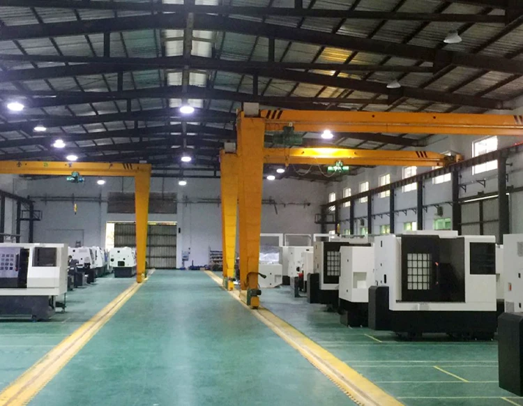
A five-axis machining center is a long-term production investment.
In addition to machine specifications, buyers should evaluate engineering communication, configuration review, inspection, installation and after-sales support.
Application-Based Machine Selection
HIRUNG reviews the customer’s workpiece information before recommending a machine configuration.
The review can include the part dimensions, material, fixture, tolerance, tool requirements and production target.
Configuration Confirmation
The spindle, CNC system, tool magazine, position feedback, probing system and coolant configuration can be confirmed before quotation.
Machine Inspection
The machine is inspected according to the agreed technical specification before shipment.
Any customer-specific acceptance requirement should be included in the technical agreement before production.
Installation and Commissioning Support
Support arrangements can be confirmed according to the machine model, destination country and project requirements.
Technical Communication
Operation documents and remote technical communication help customers handle machine setup, operation and troubleshooting.
Do not use unsupported claims such as “zero failure rate,” “best quality” or “better than every Chinese manufacturer.” Specific processes and service capabilities provide stronger purchasing evidence than general promotional statements.
Partner Brands in CNC Machines








How to Select the Right GU Series Machine
The correct five-axis machine should be selected around the workpiece and machining process rather than around a single specification.
Step 1: Provide the Part Drawing
Send a 2D drawing, 3D model or clear dimensional information.
The drawing helps the engineering team evaluate the workpiece envelope, machining directions and possible interference risks.
Step 2: Confirm the Workpiece Material
Material affects spindle selection, cutting speed, torque, tooling, coolant and machine-rigidity requirements.
Step 3: Provide Fixture Information
The total rotary-table load includes the workpiece and all clamping components.
Fixture height and shape also affect spindle access and rotary-axis movement.
Step 4: Define the Accuracy Requirement
Provide the required dimensional tolerance, positional tolerance, angular accuracy and surface-finish requirement.
Step 5: Explain the Production Target
Include the expected batch size, annual volume, cycle-time target, number of tools and automation requirements.
Step 6: Confirm the Machine Configuration
HIRUNG can then recommend a suitable GU model, spindle, CNC system, tool magazine and optional equipment.
FAQ
A 5 axis gantry universal machining center combines three linear axes with two rotary axes.
In the GU Series, the gantry-type linear axes position the spindle while the B/C rotary table tilts and rotates the workpiece. This allows the cutting tool to approach complex features from multiple directions.
The GU Series can be considered for parts containing inclined surfaces, angled holes, complex contours, deep cavities and features located on several sides.
Final suitability depends on the part dimensions, material, fixture, required tolerance and machining process.
Compare the models using the original Machine Parameters table, but do not select a machine using only table diameter or axis travel.
The complete rotating envelope, fixture weight, tool clearance, spindle requirement and machining accuracy must also be evaluated.
The machine contains three linear axes and a B/C rotary table.
The available simultaneous machining functions depend on the CNC system, machine configuration, programming software and post-processor. The required machining mode should be confirmed before ordering.
Provide the part drawing, material, maximum dimensions, fixture weight, required tolerance, surface-finish requirement and production volume.
This information allows the engineering team to evaluate the appropriate machine model and configuration.
The price depends on the selected machine model, spindle, CNC controller, tool magazine, feedback system, probing equipment, coolant configuration and other optional equipment.
Shipping destination, installation and service requirements can also affect the final quotation.
Linear scales may be considered when the application requires more direct position feedback and tighter control of positioning variation.
The need for linear scales should be evaluated according to the part tolerance, machining cycle and acceptance requirement.
Tool measurement can reduce manual tool setting and support tool-length confirmation.
It may be particularly useful when the machine uses many tools, runs longer machining cycles or requires more automated setup.
Yes. Send the part drawing together with the material, fixture information, tolerance and production requirement.
HIRUNG can use this information to recommend the GU model, spindle, CNC system and optional equipment.
The final technical agreement should clearly confirm:
- Machine model
- CNC system
- Spindle configuration
- Tool magazine
- Standard equipment
- Optional equipment
- Accuracy and acceptance conditions
- Electrical standard
- Documentation
- Installation and service arrangement