The primary disadvantages of vertical milling are constraints on workpiece size and height, inefficient chip evacuation which can harm surface finish, generally lower material removal rates compared to horizontal mills, and increased difficulty in machining complex, multi-sided parts in a single setup. While vertical milling is a cornerstone of modern manufacturing, valued for its simplicity and versatility, understanding its limitations is crucial for engineers, designers, and procurement managers to make optimal production choices. At Hirung, our expertise isn’t just in operating machines; it’s in selecting the perfect process for each unique project to guarantee precision, efficiency, and cost-effectiveness. This guide delves into the specific drawbacks of vertical milling, helping you understand when it might not be the best fit for your components.

What is Vertical Milling? A Quick Refresher
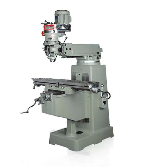
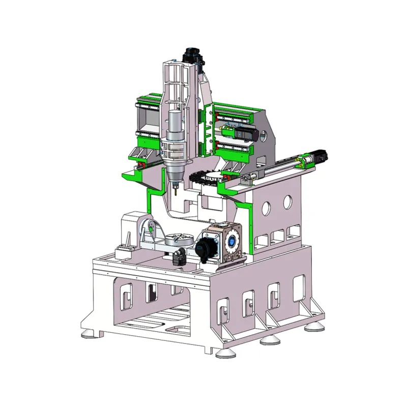
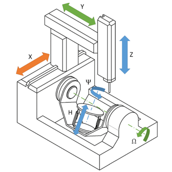
Before exploring its drawbacks, let’s quickly define vertical milling. In a vertical milling machine, the spindle axis is oriented vertically, perpendicular to the worktable. The cutting tool, held in the spindle, moves up and down along the Z-axis, while the worktable moves horizontally along the X and Y axes. This configuration is incredibly common and excels at creating 2.5D features like pockets, slots, holes, and profiles on the top surface of a part. Its straightforward setup and the operator’s clear view of the cutting action make it a workshop staple, especially for prototypes and small-to-medium production runs.
The Core Disadvantages of Vertical Milling Explained
Despite its popularity, the inherent design of a vertical mill introduces several operational limitations. These disadvantages become more pronounced when dealing with specific part geometries, high-volume production, or demanding materials. Understanding these trade-offs is key to avoiding costly production errors and delays.
Limitation 1: Constraints on Workpiece Size and Geometry
One of the most significant physical limitations of a standard 3-axis vertical mill is the maximum size and, more specifically, the height of the workpiece it can accommodate. The available machining envelope is defined by the “daylight” — the distance between the machine table and the fully retracted spindle nose. Taller parts may simply not fit. Even if a tall part fits, you must also account for the length of the tool holder and the cutting tool itself, which further reduces the usable Z-axis travel.
This makes vertical mills less suitable for large, bulky components such as large-scale enclosures, engine blocks, or substantial structural frames. The machine’s throat depth (the distance from the spindle centerline to the column) also limits the machinable width of a part. While large gantry-style vertical mills exist, the more common C-frame design presents these inherent size constraints.
Limitation 2: Inefficient Chip Evacuation and Its Consequences
What is a major operational problem with vertical milling? Chip evacuation. Because the cutting action happens on top of the workpiece, gravity works against the process. Chips (the small pieces of material removed during cutting) tend to pile up in pockets and holes instead of falling away. This seemingly small issue has several negative consequences:
- Chip Recutting: The tool can end up milling through previously cut chips, leading to excessive tool wear, increased heat, and a poor surface finish.
- Heat Buildup: Chips are a primary mechanism for carrying heat away from the cutting zone. When they accumulate, both the tool and the workpiece retain more heat, which can cause material warping and reduce tool life.
- Impaired Coolant Flow: A bed of chips can block the flow of coolant to the cutting edge, where it’s needed most. This exacerbates the problems of heat buildup and tool wear.
While high-pressure through-spindle coolant systems and air blasts can help mitigate this, they are workarounds for a fundamental design drawback. Horizontal mills, by contrast, excel here as gravity naturally helps chips fall away from the cutting zone onto the conveyor below.
Limitation 3: Reduced Material Removal Rates (MRR)
For high-volume production or the roughing of large parts, the Material Removal Rate (MRR) is a critical metric of efficiency. Generally, vertical milling machines offer lower MRR compared to their horizontal counterparts. This is primarily a function of rigidity. The C-frame design of most vertical mills is inherently less rigid than the boxier, more robust construction of a horizontal machining center (HMC).
This lower rigidity means the machine cannot withstand the immense cutting forces required for deep axial cuts or highly aggressive feed rates without risking vibration (chatter). To maintain accuracy and surface finish, operators must often program more conservative, shallower passes, which extends cycle times. HMCs, with their superior rigidity, can often take much heavier cuts, removing more material in less time, making them the preferred choice for mass production environments.
Limitation 4: Challenges with Tool Rigidity and Vibration
This point is connected to MRR but deserves its own focus. When milling deep pockets or features, a long cutting tool is required to reach the bottom without the spindle or tool holder colliding with the workpiece. In a vertical mill, this long tool extension creates a significant lever arm, making the setup much more susceptible to deflection and vibration.
Tool deflection can lead to inaccuracies—tapered walls in pockets that were designed to be straight, or features that are not perfectly to size. Vibration, or “chatter,” is even more detrimental, creating a terrible surface finish and drastically shortening the life of the cutting tool. An experienced machinist must carefully balance the tool’s length-to-diameter ratio, spindle speed, and feed rate to avoid chatter, often sacrificing cycle time for the sake of quality.
Limitation 5: Difficulty Machining Multi-Sided Parts
Imagine a part that needs features on five of its six sides. On a standard 3-axis vertical mill, this is a tedious process. The part would need to be machined on one side, then the machine stopped, the part unclamped, flipped, precisely re-located, and clamped again for the next operation. This process would be repeated for each side.
This frequent re-fixturing introduces several problems:
- Increased Cycle Time: The majority of the time is spent on manual setup, not cutting.
- Higher Labor Cost: An operator must be present for each setup change.
- Potential for Error: Every time a part is re-clamped, there’s a risk of positional inaccuracy, leading to “tolerance stack-up” where small errors from each setup accumulate into a significant final error.
While adding a 4th and 5th-axis rotary table to a vertical mill can solve this, it adds significant cost and complexity. In contrast, a horizontal mill with a built-in pallet changer and rotary B-axis is specifically designed for efficient, single-setup, multi-sided machining.
Vertical vs. Horizontal Milling: A Head-to-Head Comparison
To summarize the key differences, here is a direct comparison highlighting where each machine type typically excels or falls short.
| Feature / Consideration | Vertical Milling Machine (VMC) | Horizontal Milling Machine (HMC) |
|---|---|---|
| Ideal Workpiece | Flat parts, plates, prototypes, single-sided work (2.5D parts). | Cubic, multi-sided parts, large & heavy components. |
| Chip Evacuation | Poor. Gravity works against clearance, requiring coolant or air blasts. | Excellent. Gravity aids in clearing chips from the work area. |
| Workpiece Size | Limited by Z-axis height (“daylight”) and throat depth. | Generally accommodates larger and heavier workpieces. |
| Rigidity & MRR | Lower rigidity, leading to lower material removal rates. | Higher rigidity, allowing for more aggressive cuts and higher MRR. |
| Multi-Sided Machining | Requires multiple setups or expensive 4th/5th axis add-ons. | Excellent due to integrated rotary table (B-axis). Often automated. |
| Cost & Footprint | Generally lower initial cost and smaller footprint. | Higher initial investment and larger footprint. |
| Best Use Case | Prototyping, tool & die work, repair jobs, low-to-medium volume production. | High-volume production, automated “lights-out” manufacturing, large parts. |
When is Vertical Milling the Right Choice?
After discussing all these disadvantages, it’s essential to state that vertical milling is an incredibly capable and vital technology. It is often the perfect choice for a huge range of applications. Its strengths are the flip side of its weaknesses.
Vertical milling excels for:
- Prototypes and Short Runs: The simplicity and speed of setup make it ideal for one-off parts or small batches where the complexity of HMC programming isn’t justified.
- 2.5D Parts: For components where all features are machined from a single direction, like plates, brackets, and mold cavities, a VMC is highly efficient.
- Cost-Sensitive Projects: The lower cost of both the machine and the tooling makes it a more accessible technology.
- Ease of Use: The operator can easily see what’s happening, making manual adjustments and inspections simpler.
Conclusion: Making the Right Machining Choice with Hirung
The choice between vertical milling and other CNC processes is not about which is “better,” but about which is best for your specific part and production goals. The disadvantages of vertical milling—its size limitations, chip control issues, and lower efficiency on complex or high-volume parts—are critical factors in this decision. Ignoring them can lead to longer lead times, higher costs, and compromised quality.
Partnering with a manufacturing expert like Hirung removes the guesswork. Our team of engineers evaluates every project’s unique geometry, material, tolerances, and volume requirements. We have the expertise and the full range of CNC technology to ensure your components are produced on the right machine, the right way, every time. By understanding the limitations of each process, we leverage their strengths to deliver superior results.
Ready to transform your design into a precision-machined reality? Contact Hirung today to discuss your project with our experts and get a competitive quote.


