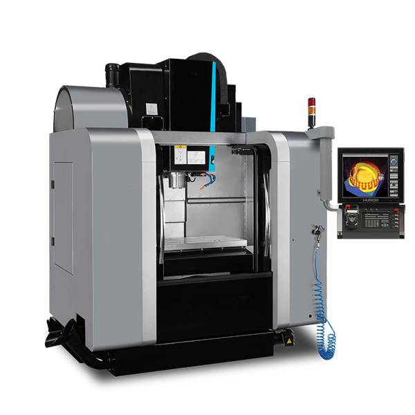
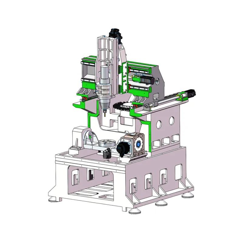
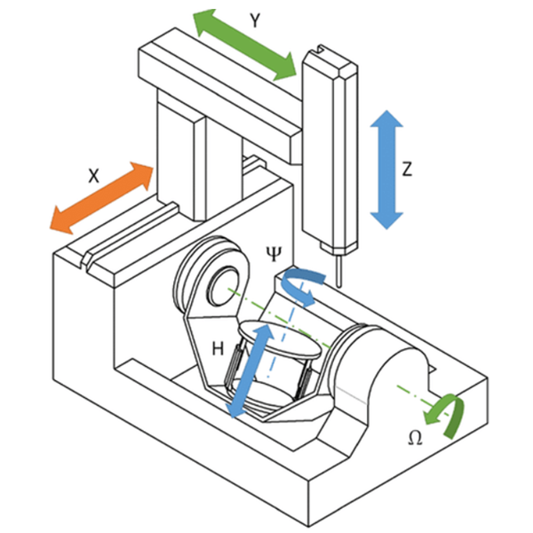
3-axis CNC machining is a subtractive manufacturing process where a computer-controlled cutting tool moves along three linear axes—X (left-right), Y (forward-backward), and Z (up-down)—to precisely remove material from a stationary workpiece and create a desired part or product. As one of the most widely used and cost-effective forms of CNC machining, this process is a cornerstone of modern manufacturing, capable of producing a vast range of parts with high precision and repeatability. It is the foundational technology for creating everything from simple brackets and housings to complex prototypes and functional components.

Understanding the Fundamentals: What Exactly is 3-Axis CNC Machining?
At its core, 3-axis CNC (Computer Numerical Control) machining automates the material removal process with incredible accuracy. The “3-axis” name refers directly to the directions of movement available to the cutting tool. Imagine a 3D graph: the tool can travel along the X-axis (horizontal), the Y-axis (vertical), and the Z-axis (depth). This synchronized movement allows the machine to carve out complex shapes and features from a solid block of material, such as metal or plastic.
The Three Linear Axes of Motion Explained (X, Y, Z)
To fully grasp how 3-axis machining works, it’s essential to understand the role of each axis. In a typical vertical milling center, which is the most common type of 3-axis machine:
- The X-axis controls the movement of the worktable from left to right.
- The Y-axis controls the movement of the worktable from front to back.
- The Z-axis controls the up-and-down movement of the spindle, which holds the cutting tool.
While the tool moves up and down (Z-axis), the table moves the workpiece beneath it (X and Y axes). The coordinated action of these three axes enables the cutter to access any point on the top surface of the workpiece, machining profiles, pockets, holes, and slots with exceptional precision.
How a 3-Axis CNC Machine Operates
The operational principle of a 3-axis CNC machine is elegantly simple but powerful. Unlike more complex 5-axis machines where the workpiece can also rotate and tilt, in 3-axis machining, the workpiece remains fixed in a single position throughout the cutting process for a given setup. The machine’s spindle, holding a rotating cutting tool (like an end mill or drill bit), moves precisely along the X, Y, and Z axes as directed by a computer program. This movement shaves away material layer by layer, progressively revealing the final shape of the part as defined in the digital design file.
The Step-by-Step 3-Axis CNC Machining Process at Hirung
Transforming a digital concept into a physical, high-precision part involves a structured and meticulous process. At Hirung, we have refined these steps to ensure efficiency, accuracy, and quality from start to finish. Here’s how we bring your designs to life.
Step 1: CAD Model Design (The Blueprint)
Every project begins with a design. Our clients provide us with a 3D CAD (Computer-Aided Design) model, which serves as the digital blueprint for the final part. This detailed model defines the exact geometry, dimensions, and tolerances required. Our engineers review the CAD file to ensure it is optimized for manufacturability (DFM), identifying any potential challenges before the machining begins to save time and reduce costs.
Step 2: CAM Programming and G-Code Generation (The Instructions)
Once the CAD model is finalized, it is imported into CAM (Computer-Aided Manufacturing) software. This is where our expert programmers translate the design into a set of machine-readable instructions. They define the toolpaths, select the appropriate cutting tools, and set parameters like cutting speed, feed rate, and depth of cut. The output of this stage is a file containing G-code and M-code, the programming language that directs every movement of the CNC machine.
Step 3: Machine Setup and Workholding (The Preparation)
This physical setup is a critical step where precision is paramount. A block of raw material (the workpiece) is securely fastened to the machine’s table using clamps, vises, or custom fixtures—a technique known as workholding. It is vital that the workpiece does not move during the high-speed cutting operation. Next, the appropriate cutting tools are loaded into the machine’s spindle, and the machine’s origin point (the “zero” reference) is precisely calibrated to match the G-code program.
Step 4: Machining Execution and In-Process Quality Control (The Creation)
With the setup complete, the machine operator initiates the program. The CNC machine autonomously executes the G-code, moving the cutting tool along the X, Y, and Z axes to precisely sculpt the material. Throughout the process, our skilled machinists oversee the operation, monitoring for tool wear and ensuring the part is being machined to specification. We conduct in-process quality checks to verify critical dimensions, ensuring that the final part perfectly matches the original CAD model and meets our stringent quality standards, which are backed by our ISO 9001:2015 certification.
Advantages and Disadvantages of 3-Axis Machining
Like any manufacturing process, 3-axis machining has a distinct set of strengths and weaknesses. Understanding these helps determine when it is the most appropriate and cost-effective choice for a project.
| Pros (Advantages) | Cons (Disadvantages) |
|---|---|
| Cost-Effective: Lower machine and programming costs make it ideal for many projects. | Geometric Limitations: Cannot machine undercuts or complex, curved surfaces in a single setup. |
| Fast Setup & Programming: Simpler setups and less complex toolpaths lead to quicker turnaround times. | Multiple Setups Required: Machining features on more than one side requires re-fixturing the part, which adds time and potential for error. |
| High Accuracy: Delivers very tight tolerances for parts with 2D and 2.5D geometries. | Limited Tool Access: The tool can only approach the part from the top (vertically). |
| Versatility: Compatible with a massive range of materials and suitable for both prototyping and production runs. | Less Efficient for Complex Parts: May not be the best choice for highly organic or intricate shapes. |
Key Benefits: Why Choose 3-Axis CNC?
The primary advantage of 3-axis CNC machining is its outstanding balance of precision and cost. Because the machines are simpler and more common than their 5-axis counterparts, both the machine time and the programming required are less expensive. This makes it the go-to process for producing parts with relatively simple geometries, such as plates, brackets, and housings. Furthermore, the simplicity of the process translates to faster setup times and programming, allowing for rapid prototyping and quicker production runs. Its ability to achieve high levels of accuracy and accommodate a vast array of materials makes it an incredibly versatile and reliable manufacturing tool.
Understanding the Limitations
The main limitation of 3-axis machining is its inability to handle complex geometric features in a single setup. Since the cutting tool only moves along three linear axes and the workpiece is stationary, it cannot machine undercuts or features on the sides of a part without manual intervention. To machine features on multiple faces, the operator must stop the machine, unclamp the part, rotate it, and then re-clamp it in a new orientation. This re-fixturing process not only adds labor time and cost but also introduces a potential for slight positional inaccuracies between features on different faces.
3-Axis vs. 5-Axis CNC Machining: Which Process Do You Need?
A common question is whether to use a 3-axis or a more advanced 5-axis machine. The choice depends entirely on part geometry, budget, and required efficiency. While 3-axis is the standard, 5-axis machining adds two rotational axes (A and B), allowing the cutting tool to approach the workpiece from a full 360 degrees in a single setup.
| Feature | 3-Axis CNC Machining | 5-Axis CNC Machining |
|---|---|---|
| Axes of Motion | X, Y, Z (linear) | X, Y, Z + A, B (rotational) |
| Ideal Part Complexity | Simple, prismatic parts, pockets, holes. | Complex contours, undercuts, multi-sided features. |
| Setup Process | Potentially multiple setups for multi-sided parts. | Often a single setup (“done-in-one”). |
| Cost | Lower. More cost-effective for suitable parts. | Higher. More expensive machine time and programming. |
| Accuracy | High, but re-fixturing can introduce error. | Extremely high, as single setup eliminates tolerance stack-up. |
When is 3-Axis the Right Choice?
You should choose 3-axis machining when your parts have features primarily on a single face or can be easily machined with a few simple rotations. It is the perfect solution for:
- Rapid Prototyping of initial concepts.
- Machining Parts with Shallow Cavities and simple profiles.
- Creating Jigs, Fixtures, and Mounts where prismatic shapes are common.
- Cost-Sensitive Projects that do not require the complexity of 5-axis machining.
- Drilling, Tapping, and Milling operations on flat or gently contoured surfaces.
When to Upgrade to 4-Axis or 5-Axis Machining?
It’s time to consider Hirung’s more advanced 4-axis or 5-axis capabilities when your project demands higher efficiency for complex parts. Upgrade if your part has deep pockets, contoured surfaces (like those found in turbine blades or medical implants), or features on four or five faces. 5-axis machining can complete such a part in a single setup, which not only improves accuracy by eliminating re-fixturing errors but can also be faster and more cost-effective in the long run for highly complex geometries.
Common Applications and Industries Served by 3-Axis Milling
The versatility and cost-effectiveness of 3-axis CNC milling make it indispensable across numerous industries. At Hirung, we leverage this technology to produce critical components for a wide range of sectors:
- Aerospace: Brackets, housings, panels, and fixtures that require high precision but not necessarily complex contouring.
- Automotive: Prototyping of engine components, jigs for assembly lines, and custom parts for racing applications.
- Medical: Enclosures for electronic medical devices, surgical tools, and custom orthotics.
- Electronics: Heatsinks, enclosures, faceplates, and custom hardware for consumer and industrial electronics.
- Robotics & Automation: Structural components, mounting plates, and custom actuator parts.
Materials We Machine Using the 3-Axis Process
Our 3-axis CNC machines are capable of handling a diverse portfolio of materials to meet any project specification. We have extensive experience machining:
- Metals: Aluminum (e.g., 6061, 7075), Stainless Steel (e.g., 303, 304, 316), Carbon Steel, Brass, Copper, and Titanium.
- Plastics: ABS, Polycarbonate (PC), Nylon, Delrin (POM), PEEK, and Acrylic (PMMA).
- Other Materials: We can also accommodate requests for other specialized materials. Contact our engineering team to discuss your specific needs.
Partner with Hirung for Your 3-Axis CNC Machining Projects
Since 2011, Hirung has been a trusted leader in providing high-quality CNC machining services. The 3-axis CNC machining process is a core part of our expertise, allowing us to deliver precise, affordable parts with impressive speed. Our commitment to excellence is demonstrated through our state-of-the-art equipment, a team of highly skilled engineers and machinists, and our rigorous ISO 9001:2015 certified quality management system.
We are more than just a supplier; we are your manufacturing partner. Whether you need a single prototype or a full production run, we are equipped to handle your project with the professionalism and attention to detail it deserves. Let us put our experience to work for you.


