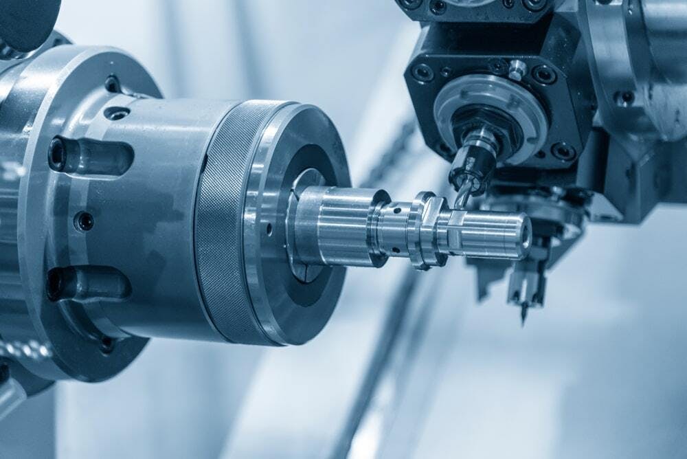
Is your machining center delivering the precision you expect? In industries like aerospace, automotive, and medical device manufacturing, positioning accuracy of a machining center is the difference between flawless parts and costly rejects. Positioning accuracy refers to a machine’s ability to move its components—spindle, table, or tool—to the exact coordinates commanded by the CNC system. Even minor deviations can lead to defective parts, downtime, or scrapped materials. To ensure your machine performs at its peak, you need reliable methods to detect and verify its accuracy.
This guide explores seven ways to detect positioning accuracy of a machining center, from high-tech laser systems to practical on-machine probing. Whether you’re a CNC operator, technician, or shop manager, these methods will help you maintain precision and boost productivity. Let’s dive in and uncover how to keep your machining center on point.

Method 1: Laser-Based Measurement
What It Is
Laser-based measurement uses interferometry to assess linear displacement errors along a machining center’s axes, offering unmatched precision for CNC positioning accuracy.
How It Works
A laser interferometer emits a beam that travels along the machine’s axis, reflecting off a target to measure deviations between commanded and actual positions. Systems like the Renishaw XL-80 calculate errors in real-time, often to within 0.5 micrometers (μm).
Equipment Needed
- Laser interferometer (e.g., Renishaw XL-80 or API XD Laser).
- Optical components (retroreflectors, beam splitters).
- Calibration software for data analysis.
Pros
- High Precision: Detects errors as small as 0.5μm, ideal for aerospace or mold-making.
- Industry-Standard: Aligns with ISO 230-2 for positioning accuracy tests.
- Comprehensive: Measures linear and angular errors across multiple axes.
Cons
- Costly: Equipment and setup can exceed $50,000.
- Expertise Required: Needs trained technicians for accurate results.
- Time-Intensive: Setup and calibration take hours.
When to Use
Use laser measurement for high-precision applications or when certifying a new machining center. For example, a shop producing turbine blades might use this method to ensure tolerances below 0.01mm.
Method 2: Ballbar Testing
What It Is
Ballbar testing evaluates a machining center’s ability to follow circular paths, revealing errors in machining center accuracy during multi-axis movements.
How It Works
A telescoping ballbar, such as the Renishaw QC20-W, is mounted between the spindle and table. The machine executes a circular path, and the ballbar measures deviations from the ideal circle, identifying issues like backlash, servo mismatch, or squareness errors.
Equipment Needed
- Ballbar system (e.g., Renishaw QC20-W or Heidenhain DB 4.0).
- Analysis software (typically included with the system).
- Fixturing kit for secure mounting.
Pros
- Multi-Axis Insight: Detects errors in X-Y, Y-Z, or X-Z planes.
- Quick Setup: Tests can be completed in under an hour.
- Diagnostic Power: Pinpoints specific issues like stick-slip or scaling errors.
Cons
- Limited Scope: Focuses on circular interpolation, not linear accuracy.
- Moderate Cost: Systems cost $10,000–$20,000.
- Requires Training: Interpreting results demands technical knowledge.
When to Use
Ideal for routine maintenance or diagnosing interpolation issues. For instance, a shop noticing uneven contours in molded parts might use ballbar testing to troubleshoot.
Method 3: Dial Indicator Measurements
What It Is
Dial indicator measurements are a manual, cost-effective way to check how to check CNC machine accuracy, focusing on backlash and repeatability.
How It Works
A dial indicator is mounted on a magnetic base and positioned against a reference surface (e.g., the table or a test bar). The machine moves to specific positions, and the indicator measures deviations, revealing issues like backlash or axis drift.
Equipment Needed
- Dial indicator (e.g., Mitutoyo 2046S, 0.01mm resolution).
- Magnetic base or fixture.
- Test bar or reference block.
Pros
- Affordable: Equipment costs under $500.
- Simple Setup: Requires minimal training.
- Versatile: Works on any machining center.
Cons
- Lower Precision: Limited to 0.01mm resolution.
- Time-Consuming: Manual measurements are slow.
- Operator-Dependent: Accuracy varies with user skill.
When to Use
Best for small shops or initial troubleshooting. For example, a technician noticing part misalignment might use a dial indicator to check for excessive backlash.
Method 4: Linear Encoder Calibration
What It Is
Linear encoder calibration verifies machining center calibration by comparing commanded positions to feedback from linear scales, ensuring precise axis movement.
How It Works
Linear encoders, embedded along the machine’s axes, provide high-resolution position feedback. Calibration involves moving the machine to known positions and comparing encoder data to commanded values, often using software to log errors.
Equipment Needed
- Linear encoders (pre-installed on modern machines).
- Calibration software (e.g., Heidenhain TNCremo).
- Reference standards (e.g., gauge blocks).
Pros
- Direct Measurement: Assesses axis performance accurately.
- Reliable: Encoders are less affected by thermal expansion.
- Automated: Software simplifies data collection.
Cons
- Encoder Dependency: Only works on machines with linear scales.
- Setup Cost: Retrofitting encoders is expensive.
- Limited Scope: Focuses on linear axes, not angular errors.
When to Use
Use for machines with built-in encoders, like a 5-axis machining center producing precision molds, to verify axis accuracy.
Method 5: Grid Encoder Testing
What It Is
Grid encoder testing assesses precision testing for CNC machines across a 2D plane, ideal for large worktables or multi-axis systems.
How It Works
A grid encoder, such as the Heidenhain KGM, is placed on the machine table. The spindle moves across a grid pattern, and the encoder measures positional deviations in X and Y axes, detecting errors like squareness or scaling.
Equipment Needed
- Grid encoder system (e.g., Heidenhain KGM 282).
- Analysis software for mapping errors.
- Stable fixturing for the encoder plate.
Pros
- Comprehensive: Tests positioning across a wide area.
- High Accuracy: Detects errors to within 1μm.
- Multi-Axis Capability: Assesses X-Y plane interactions.
Cons
- Complex Setup: Requires precise alignment and calibration.
- High Cost: Systems can cost $30,000+.
- Specialized Use: Less common in smaller shops.
When to Use
Perfect for large machining centers or high-accuracy applications, like a shop producing semiconductor fixtures with flatness requirements.
Method 6: Standardized Test Procedures (ISO 230-2)
What It Is
Standardized test procedures, such as ISO 230-2, provide a globally recognized framework for measuring CNC positioning accuracy and repeatability.
How It Works
ISO 230-2 outlines tests to measure positioning accuracy and repeatability along each axis. These involve moving the machine to a series of positions, measuring deviations with tools like lasers or indicators, and calculating metrics like bidirectional accuracy (A) and repeatability (R).
Equipment Needed
- Varies by test (e.g., laser interferometer, dial indicator).
- Calibration software compliant with ISO standards.
- Reference standards for traceability.
Pros
- Globally Accepted: Ensures compliance with industry benchmarks.
- Repeatable: Structured tests allow consistent results.
- Versatile: Adaptable to different machine types.
Cons
- Knowledge Barrier: Requires familiarity with ISO standards.
- Time-Intensive: Full tests can take hours or days.
- Equipment Variety: May need multiple tools for comprehensive testing.
When to Use
Use for certification, customer audits, or compliance checks. For example, a shop supplying aerospace parts might run ISO 230-2 tests to meet contractual standards.
Method 7: On-Machine Probing
What It Is
On-machine probing uses touch probes to verify machining center accuracy in real-time, directly on the workpiece or fixture.
How It Works
A touch probe, such as the Renishaw OMP40, is mounted in the spindle. The machine moves to programmed positions, and the probe measures actual coordinates, detecting deviations caused by positioning errors or thermal drift.
Equipment Needed
- Probing system (e.g., Renishaw OMP40 or Blum TC50).
- CNC control software with probing cycles.
- Reference workpiece or datum feature.
Pros
- Integrated: Performed within the machine’s workflow.
- Practical: Measures accuracy under real conditions.
- Fast: Quick checks during production runs.
Cons
- Probe Limitations: Accuracy depends on probe calibration (typically 1–2μm).
- Surface Dependency: Requires clean, stable surfaces.
- Not Comprehensive: May miss systemic axis errors.
When to Use
Ideal for in-process verification, like a shop producing automotive gears checking positioning during setup.
Comparison of the Seven Methods
To choose the right method for your machining center, consider accuracy, cost, complexity, and application. Here’s a comparison:
| Method | Accuracy | Cost | Complexity | Best For |
| Laser-Based Measurement | 0.5μm | High ($50,000+) | High | High-precision calibration |
| Ballbar Testing | 1μm | Medium ($10,000–$20,000) | Medium | Multi-axis diagnostics |
| Dial Indicator Measurements | 10μm | Low ($500) | Low | Small shops, initial checks |
| Linear Encoder Calibration | 1μm | Medium (if equipped) | Medium | Machines with encoders |
| Grid Encoder Testing | 1μm | High ($30,000+) | High | Large tables, 2D accuracy |
| ISO 230-2 Tests | Varies | Varies | High | Certification, compliance |
| On-Machine Probing | 1–2μm | Medium ($5,000–$15,000) | Low | In-process verification |
Choosing the Right Method: For routine maintenance, ballbar testing or probing is efficient. For certification, laser or ISO 230-2 tests are ideal. Small shops may prefer dial indicators for cost savings, while high-precision shops invest in laser or grid encoder systems.
Conclusion
Detecting the positioning accuracy of a machining center is critical to ensuring part quality, minimizing waste, and maintaining competitiveness. From laser interferometry’s precision to the practicality of on-machine probing, these seven methods offer solutions for every shop’s needs and budget. Regular accuracy checks not only prevent defects but also extend machine life. Ready to optimize your machining center’s performance? Start with one of these methods or consult a precision equipment provider like HIRUNG for tailored solutions.


