A CNC gantry machine is used for large workpiece machining because its bridge-like structure leaves the sides and top of the work zone open, supports long X-axis travel without forcing a table to carry the part, and keeps heavy components stable while the tool reaches every face. Instead of moving the workpiece under a fixed spindle, a gantry moves the cutting head overhead, which is exactly the layout large parts demand.
CNC gantry machines are preferred for large workpieces because they combine an open work envelope, long travel, high load capacity, and stable overhead cutting access that conventional vertical or horizontal centres cannot match.
That matters once a part exceeds the table, weight or reach limits of a conventional machining centre. Mould bases, aerospace structural ribs, energy-sector casings, shipbuilding frames and construction machinery booms all share one thing: they are too large or too heavy to be repositioned easily. The right machine lets you machine them in fewer setups, with less crane time and more predictable accuracy. This article explains why the gantry layout is the standard answer, and how HIRUNG CNC gantry machining centres translate that layout into published specifications.
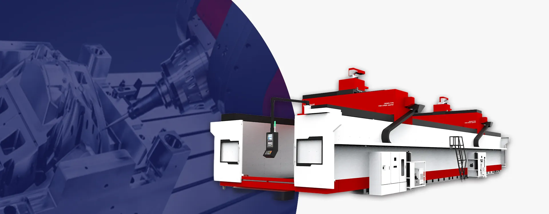
What Counts as a “Large” Workpiece?
Large is a relative term in machine shops. A 400 mm mould insert can be large to a precision cell, while a 12-metre ship frame is routine at a heavy-equipment supplier. For gantry-machine selection, three dimensions matter.
A workpiece becomes a gantry candidate when its envelope, mass or multi-face setup requirements exceed what a moving-table machining centre can handle.
Envelope: the space the tool must reach
The workpiece envelope is the smallest box that contains every point the cutter must touch, including clearance for angled heads, probes and fixtures. A part becomes a gantry candidate when its envelope exceeds the travel of a vertical or horizontal machining centre, especially in the X direction.
Mass: table load versus floor load
Mass matters because it determines whether the table can carry and accelerate the part reliably. On a moving-table gantry, table load is a hard ceiling. On a moving-column gantry, the part sits on the floor, so the practical limit becomes the foundation and crane capacity, not a table rating.
Setup complexity: how many faces must be machined
Large parts often need machining on five faces. Repositioning a multi-tonne workpiece is slow, expensive and a source of error. A machine that can reach multiple faces in one clamping pays back quickly, even if the capital cost is higher.
| Workpiece characteristic | Why it pushes you toward a gantry |
|---|---|
| Long structural parts (>3 m in one axis) | X-axis travel on conventional machines is quickly exhausted; gantry columns can be spaced metres apart. |
| Heavy mould bases or energy casings | Table loads exceed moving-table ratings; floor-load gantry designs remove the table constraint. |
| Multi-face housings and frames | Overhead spindle and angle-head access reduce repositioning. |
| Thin-walled aerospace or large frames | Rigid closed-loop frame and hand-scraped guideways reduce vibration over long cuts. |
Why the Gantry Layout Solves the Large-Part Problem
The gantry design inverts the conventional layout. In a vertical machining centre, the table moves in X and Y while the spindle stays overhead. In a gantry, the spindle is carried on a crossbeam between two columns, and the part sits beneath it. That inversion creates four practical advantages for large workpieces.
Open access for loading and fixturing
Because the gantry spans the work zone rather than enclosing it, cranes and forklifts can reach the table or floor plate from the front and sides. This is not a minor convenience on a part that weighs several tonnes; it directly affects setup time and operator safety.
Long travel without moving the part
The main advantage of a CNC gantry machine for large parts is that the structure grows in length without forcing the table to carry and move the entire workpiece. HIRUNG publishes HPG Series travel up to 12,200 mm, with 12,000 mm+ travel available, while the SP Series covers X travel from 1,600 mm to 24,000 mm on the largest model. Once the table stops moving, the travel length is limited mainly by the bed and guideway design, not by inertia.
Overhead spindle reach
The spindle hangs from the crossbeam and can be extended on the Z axis to machine deep cavities or to clear tall fixtures. On large parts, that reach is often more useful than rapid traverse speed.
Closed-loop rigidity
The two columns and the crossbeam form a rigid loop that resists the cutting forces generated when taking deep cuts in steel or cast iron. For large, rigid parts, the machine must be stiffer than the part it is cutting, or chatter will dominate.
| Machine type | Typical X/Y/Z travel | How the part is supported | Best for |
|---|---|---|---|
| Vertical machining centre | Up to roughly 2,000 × 800 × 700 mm on large models | Moving table, table load limited | Small-to-medium parts at volume, quick changeover |
| Horizontal machining centre | Similar to VMC, pallet-based | Pallet and tombstone, good for boxy parts | Prismatic parts in batches, four-sided access |
| Moving-table gantry | X from 1,600 mm to 24,000 mm depending on model | Table carries the part, fixed bridge above | Large moulds, aerospace structures, finishing-focused work |
| Moving-column gantry | X up to 12,000 mm+ | Part rests on the floor or a stationary platen | Very large or very heavy energy and shipbuilding components |
The Two Gantry Architectures for Large Workpieces
Not every large part needs the same gantry layout. The choice between moving table and moving column depends on what is limiting your process: the envelope, the weight, or the finish requirement.
Choose a moving-table gantry when finishing accuracy matters most, and a moving-column gantry when part weight or size would overwhelm any moving table.
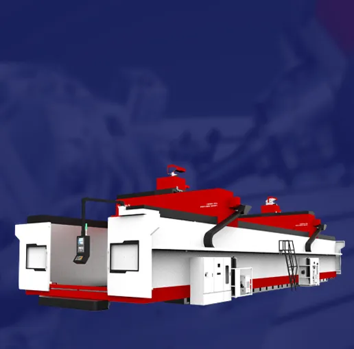
Moving-table gantry: fixed bridge, table carries the part
In this layout, the bridge stays fixed and the table moves the part through the cut. The advantage is a very rigid, vibration-damped bridge, which is ideal for finishing large mould surfaces or aerospace structural parts to tight tolerances. The constraint is that the table must accelerate and decelerate the part, so table load is a real limit.
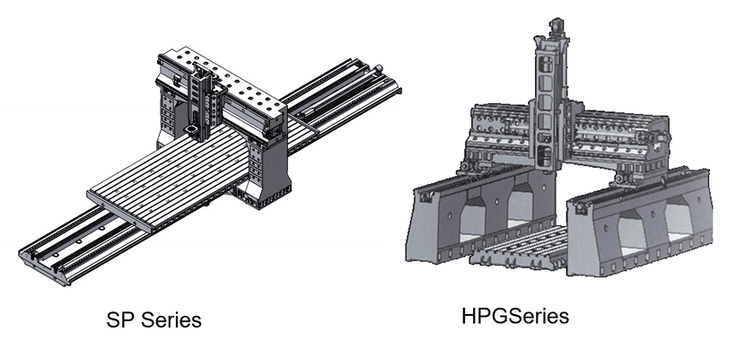
HIRUNG’s SP Series table-moving gantry centres use a Meehanite-structured integrated bed that is annealed for stress relief, precision roller linear slides on X and Y, and a hardened box way on Z. Published table loads range from 4,000 kg on the SP1615 to 20,000 kg on the SP6039, with X travel extending up to 24,000 mm on the largest model. The design is clearly aimed at large precision parts rather than raw tonnage.
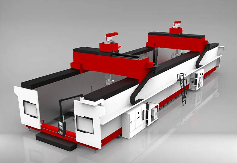
Moving-column gantry: fixed table, columns travel over the part
Here the table is stationary and the gantry columns travel along rails on either side of the work zone. Because the part does not move, load capacity is governed by the foundation and the floor plate, not by a table motor. This is the layout used when parts are so large or so heavy that no table could carry them.
HIRUNG’s HPG Series column-moving gantry centres use a floor-type configuration with a patented box-in-box crossbeam, four Z-axis guideways, and a dual servo direct drive on the long axis. Published travel reaches 12,200 × 3,000 × 1,200 mm on the HPG12030, and machine weight runs up to 115 tonnes on that model. The guideways are positioned above the workpiece to protect them from chips and coolant, and HIRUNG states the footprint can be reduced by up to 60% versus a comparable moving-table machine.
| Decision point | Moving-table (SP-like) | Moving-column (HPG-like) |
|---|---|---|
| Where the load sits | On a moving table, governed by table load rating | On the floor or platen, governed by foundation |
| Best fit | Large moulds, aerospace structures, high-precision finishing | Extra-large energy equipment, shipbuilding, very heavy frames |
| Rigidity priority | Fixed bridge gives high inherent damping | Constant moving mass, dual servo on long axis |
| Travel envelope | X up to 24,000 mm on the largest SP model | X up to 12,000 mm+ on the HPG Series |
| Floor space | Needs clearance for table travel | Smaller footprint for the same working envelope |
| Typical workpiece mass | 4,000 kg to 20,000 kg per model | Virtually unlimited, depending on foundation |
Structural Design Features That Hold Accuracy on Large Parts
A large machine is only useful if it is still accurate at the far ends of its travel. Accuracy on a gantry is a structural problem: long beams deflect, thermal growth shifts the spindle, and interrupted cuts excite vibration. HIRUNG addresses these with a combination of material choice, assembly process and active thermal control.
On a large gantry, long-term accuracy depends more on thermal control, hand-scraped joints and crossbeam rigidity than on the spindle speed rating.
Mehanite cast iron and stress relief
HIRUNG gantry structures use high-grade Mehanite cast iron, heat-treated for stress relief. Cast iron is chosen for damping as much as for stiffness; it absorbs the vibration that heavy interrupted cuts generate. The structures go through casting, tempering, rough machining, finish machining, painting and final machining before assembly, which removes much of the internal stress that would otherwise distort the machine over time.
Hand-scraped joint surfaces
Critical mounting faces are hand-scraped to hold the guideway mounting face to within 0.01 mm per 1,000 mm. Hand scraping is slow and cannot be faked, but it is the traditional way to ensure that the guideway sits flat against the casting over a long distance.
Box-in-box crossbeam
The crossbeam and Z-axis ram are the longest lever arms in the structure. On the HPG Series, the patented box-in-box crossbeam with four Z-axis guideways is intended to resist the moment created when the ram is extended. On any large gantry, the way the crossbeam is supported at each end matters more than the beam’s weight alone.

Hardened box ways versus linear guides
Heavy milling favours damping, which points toward hardened box ways. High-speed finishing and intricate 3D surfaces favour responsiveness, which points toward linear guides. HIRUNG offers hardened box ways at HRC 50+ for heavy milling alongside premium linear guideways, and the SP Series combines both: roller guides on X and Y and a hardened box way on Z. The message is that the guideway mix should match the work mix, not the brochure.
Spindle oil cooling and thermal stability
Thermal growth is the largest single source of dimensional drift on a large machine. Spindle oil cooling is fitted as standard across the HIRUNG gantry range, with the stated aim of keeping Z-axis thermal displacement below 0.005 mm. Without that control, the first part of a shift can measure differently from the last.
Verification to a named standard
HIRUNG publishes full-travel figures of roughly 0.010 mm positioning and ±0.003 mm repeatability for the gantry range, verified with laser interferometer and ballbar testing, with SP Series positioning and repeatability quoted to VDI 3441. The key point for buyers is not the number alone, but that it is tied to a measurement standard and a full-travel length.
| Structural feature | What it does for large workpieces | How HIRUNG implements it |
|---|---|---|
| Bed material | Absorbs vibration and retains stability | Mehanite FC300 / GC-275, heat-treated and stress-relieved |
| Guideway mounting | Maintains straightness over long travel | Hand-scraped joint surfaces to 0.01 mm / 1,000 mm |
| Crossbeam rigidity | Resists moment when the ram is extended | Box-in-box crossbeam with four Z-axis guideways on HPG |
| Thermal control | Keeps dimensions stable across shifts | Spindle oil cooling standard, <0.005 mm Z-axis thermal displacement |
| Accuracy verification | Gives a measurable basis for acceptance | Laser interferometer and ballbar testing, VDI 3441 on SP Series |
| Load handling | Supports very heavy parts without table limits | Moving-column floor-type layout on HPG; table loads up to 20,000 kg on SP |
Typical Industries and Workpieces for Large Gantry Machining
The same structural features make gantry machines useful across several industries. The workpieces differ, but the common thread is always size, weight or geometric complexity.
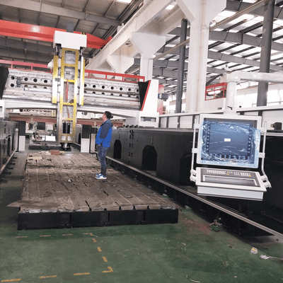
| Industry | Typical large workpieces | Why a gantry fits |
|---|---|---|
| Mould and die | Large mould bases, cavity blocks, stamping dies | Long X travel, fixed-bridge damping, good surface finish |
| Aerospace | Wing ribs, bulkheads, landing gear beams, structural frames | Multi-face access, tight tolerances over long parts, low vibration |
| Energy and shipbuilding | Turbine housings, gearboxes, propulsion components, hull sections | Very large envelope, floor-load capacity for multi-tonne parts |
| Construction machinery | Booms, frames, buckets, weldments | Heavy roughing, long parts, cast iron damping |
| Medical instruments | Large instrument housings, precision fixturing plates | Micron-level repeatability over a large work zone |
HIRUNG lists mould and die, aerospace and medical instruments as core applications on its gantry machining centre page. Construction machinery and energy/shipbuilding workpieces fit the HPG Series because they push the envelope and mass limits, while aerospace and mould work tends to favour the SP Series for finishing accuracy.
How to Match a Gantry Machine to Your Large Workpiece
Knowing why gantry machines are used is not the same as knowing which one to specify. The specification order is straightforward once the part is defined.
The right gantry for a large workpiece is the one whose architecture, travel envelope, load path and guideway mix match the largest and heaviest parts you expect to machine.
| Specification step | Question to answer | What to look for |
|---|---|---|
| 1. Envelope | What is the largest part you will quote in the next three to five years? | Add clearance for fixtures and angle heads; size travel, not table, first |
| 2. Load path | Will the part sit on the floor or on a moving table? | Moving-column if mass dominates; moving-table if finishing accuracy dominates |
| 3. Material removal | Is the work roughing, finishing, or mixed? | Gearbox spindles and box ways for roughing; linear guides and thermal control for finishing |
| 4. Accuracy | What tolerance must you hold over what travel length? | Full-travel figures tied to a named standard such as VDI 3441 or ISO 230-2 |
| 5. Installation | Can your floor, crane and power supply support the machine? | Foundation design must run in parallel with machine manufacture |
| 6. Lifecycle support | Who services the machine and stocks parts in your region? | Service coverage, spare-parts lead times and training |
Common Mistakes When Moving to Gantry Machining
The most expensive mistake is buying a gantry that is the right size on paper but the wrong architecture for your parts.
| Mistake | Why it happens | What it costs |
|---|---|---|
| Specifying only for today’s largest part | Short-term quoting horizon | Turning away larger work within two years |
| Confusing table load with point load | Part weight is near the published maximum, concentrated in one area | Deflection, poor finish and unpredictable accuracy |
| Prioritising rapid traverse over torque | Marketing highlights m/min figures | Fast moves between slow cuts on heavy material |
| Ignoring thermal behaviour | Oil cooling is treated as optional | Parts measure differently across the shift |
| Under-budgeting installation | Capital budget covers only the machine | Months between delivery and first chip |
| Treating accuracy figures as universal | Quoted number is not tied to a standard or travel length | No acceptance criteria when tolerance is missed |
Frequently Asked Questions
Why are CNC gantry machines used for large workpiece machining?
They are used because the overhead crossbeam leaves the work zone open for crane loading, supports long X-axis travel without moving the part, and keeps heavy workpieces stable while the tool reaches multiple faces in one setup.
What is the difference between a moving-table and a moving-column gantry machine?
A moving-table gantry has a fixed bridge and a table that carries the part, which is ideal for high-precision finishing but limited by table load. A moving-column gantry has a stationary table or floor plate and travelling columns, which is the better choice when parts are very large or very heavy.
Can a CNC gantry machine handle multi-tonne workpieces?
Yes. Moving-column floor-type gantries are designed so the workpiece rests on the floor rather than on a moving table, which removes the table load limit. On HIRUNG’s HPG Series, the load is effectively governed by the foundation and floor plate.
How accurate is a CNC gantry machine over long travel?
Accuracy depends on the machine’s structure, thermal control and the measurement standard used. HIRUNG publishes full-travel positioning accuracy of roughly 0.010 mm and repeatability of ±0.003 mm, verified with laser interferometer and ballbar testing.
Which industries use CNC gantry machines for large parts?
Mould and die, aerospace, energy and shipbuilding, construction machinery, and medical instruments all use gantry machines when parts exceed the size, weight or accuracy envelope of conventional machining centres.
Is a gantry machine better than a vertical machining centre for large parts?
For parts beyond the table or travel limits of a vertical machining centre, a gantry is usually the better choice because it offers a much larger envelope and can machine heavy parts in fewer setups. For smaller parts at volume, a vertical machining centre is typically faster and cheaper.
What should I check before buying a CNC gantry machine for large parts?
Confirm the travel envelope, table or floor load path, spindle torque curve, guideway mix, thermal control, accuracy standard, foundation requirements and service coverage. Match these to your largest and heaviest expected workpiece, not just to today’s jobs.
Final Takeaway
CNC gantry machines are not simply bigger versions of vertical machining centres. They are a different layout chosen because the part cannot be moved easily, the travel cannot be shortened, or the tolerance cannot be compromised over a long distance. The right architecture — moving table or moving column — depends on whether your constraint is finishing accuracy or part size and weight.
If your work is moving into mould bases, aerospace structures, energy components or construction machinery frames, the CNC gantry machining centre range at HIRUNG covers both architectures: the column-moving HPG Series for oversized and very heavy work, and the fixed-bridge SP Series for high-precision large-part finishing. Share your part drawings, material and tolerance band, and the engineering team can confirm which configuration fits before you commit to the foundation.