Choosing between a trunnion table and a swivel head configuration is the primary kinematic decision when investing in 5 axis machining centers. The direct answer comes down to workpiece geometry, mass, and cutting forces: trunnion table architectures excel at producing small-to-medium, highly intricate parts requiring aggressive undercut access and maximum dynamic accuracy, whereas swivel head architectures are engineered for large, heavy components where table tilting would cause geometric deflection or physical enclosure collisions.
Selecting the wrong mechanical configuration leads to severe operational bottlenecks, including unmanageable tool overhang, spindle-to-table collisions, or premature drive wear. This guide breaks down the kinematic differences, compares structural stiffness and rotary boundaries, maps industrial part profiles to the ideal platform, and provides a clear decision framework to match machine architecture to your specific production requirements.
Machine Kinematics Explained: Table-Table vs. Head-Table Configurations
Every 5-axis CNC machining center operates on three linear axes (X, Y, Z) and two rotary axes selected from A (tilting around X), B (tilting around Y), and C (continuous rotation around Z). The defining architectural difference lies in whether those rotary motions occur entirely at the workpiece, entirely at the cutting tool, or are split between the two.
Trunnion Architecture (Table-Table / Trunnion-Style)
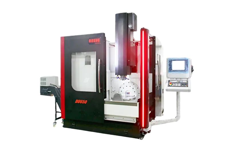
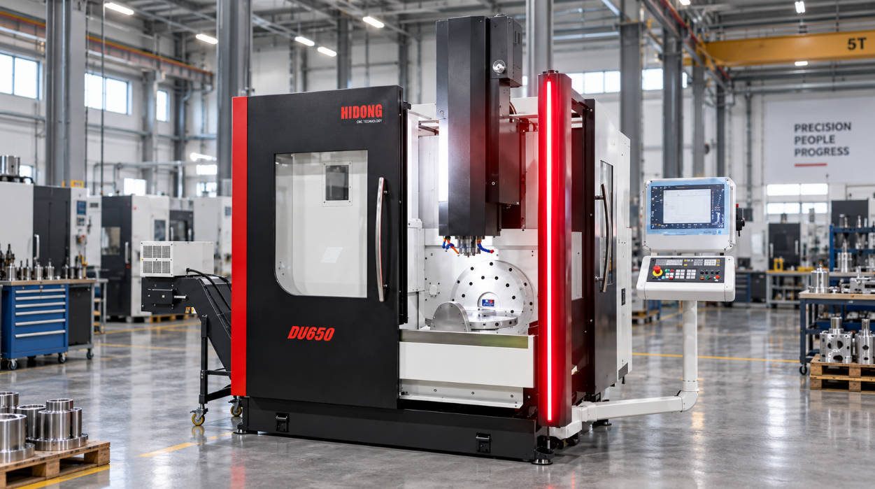
In a trunnion-style machine, the cutting spindle moves strictly along the primary linear axes (typically X, Y, and Z), while both rotational degrees of freedom reside on the worktable. A dedicated cradle—the trunnion—tilts along the A or B axis, housing an integrated rotary platter that indexes or rotates continuously along the C axis.
Because the cutting head remains fixed in orientation, the center of cutting forces directs upward through a rigid, vertical column. The workpiece swings and tilts beneath the tool. This configuration isolates spindle bearings from off-axis rotational loads, but it requires that every degree of rotary tilt displaces the entire mass of the workpiece, fixturing, and chucking mechanisms.
Swivel Head Architecture (Head-Table / Articulated-Head)
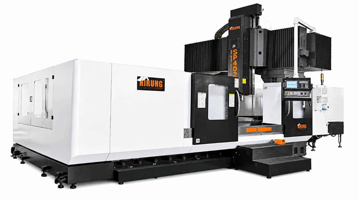
A swivel head machine redistributes or fully assigns rotary movement to the tool spindle. In a classic head-table (hybrid) configuration, the spindle housing tilts along the B or A axis, while the workpiece sits on a horizontal C-axis rotary platter embedded in a stationary bed. In pure head-head setups, both rotary axes reside in an articulated wrist housing above the table.
Because the cutting tool articulates around the part, the worktable remains completely horizontal or rotates around a single vertical centerline. This design removes dynamic tilt forces from the workpiece base, allowing the machine to support substantial component weights without tilting backlash. However, tilting the spindle head changes the orientation of the cutting tool relative to machine thermal growth vectors, placing high mechanical demands on rotary joint rigidity and tool-center-point management (RTCP).
Performance Breakdown: Comparing Trunnion and Swivel Head Across 5 Key Metrics
Evaluating both kinematic styles against practical manufacturing parameters highlights where structural compromises emerge under load.
1. Workpiece Dimensions & Weight Capacity
Workpiece envelope represents the clearest technical boundary between these configurations:
- Trunnion Tables: The maximum workpiece diameter is physically constrained by the space between the trunnion support arms (trunnion walls). Furthermore, as the table tilts toward 90 degrees, an off-center or heavy workpiece exerts significant cantilevered torque on the rotary drive motors and brakes. Exceeding rated table payloads causes servo oscillation, dynamic positioning lag, and increased mechanical wear.
- Swivel Heads: Because the table surface does not tilt, the machine bed can support heavy billet stock, forgings, and massive castings. Machine capacity is governed strictly by linear guideway load ratings and static table limits rather than rotary motor holding torque.
2. Cutting Rigidity, Tool Overhang, and Chatter Control
Tool deflection is directly proportional to the cube of tool overhang ($L^3$). Machine geometry determines how close the spindle nose can get to the cutting zone:
- Trunnion Machines: The workpiece tilts toward the spindle nose, allowing tools to approach sidewalls, pockets, and compound angles using standard, stubby end mills. Shorter tool projection maximizes tool assembly stiffness, suppresses harmonic chatter, and permits aggressive feeds when roughing tough materials.
- Swivel Head Machines: Tilting the large spindle housing near an expansive, flat workpiece can introduce clearance issues between the spindle casting and the part. To reach recessed features or internal pockets at steep angles, machinists often must extend tool projection lengths. Longer tool reach diminishes dynamic cutting stiffness, requiring conservative radial engagement depths to prevent surface vibration.
3. Rotary Travel Limits and Clearance
Physical kinematics dictate how freely a five-axis simultaneous cut can proceed without axis-limit stops:
- Trunnion configurations commonly offer extensive tilt ranges (often +30° to -120° or wider, depending on machine design), making them suited for five-sided machining and deep undercuts in a single setup. However, tall workpieces swing in a wide circular arc, raising the risk of collision with machine sheet metal or tool changers.
- Swivel head configurations maintain a consistent workpiece boundary, as the part does not swing through the machine enclosure. Conversely, the articulated head’s rotational range is often limited by internal routing lines, coolant hoses, and spindle casting geometry, which can limit undercut accessibility on compact geometries.
4. Dynamic Accuracy and Thermal Expansion Management
Both configurations present distinct thermal and dynamic error vectors:
- In trunnion designs, the pivot point sits low beneath the part. Any angular tracking error in the A/B tilt axis amplifies linearly as the distance from the table surface to the cutting point increases ($E = R \cdot \theta$). Thermal expansion primarily moves along the vertical Z-axis column, which is straightforward for standard CNC compensation algorithms to track.
- In swivel head designs, the tool pivot point is located close to the spindle face. However, continuous rotational movement in the head generates internal bearing and motor heat directly adjacent to the cutting tool. Multi-axis thermal growth vectors are more complex to measure and offset dynamically, requiring high-resolution scale feedback and advanced thermal monitoring to maintain sub-micron positioning.
Machine Architecture Comparison Table
| Engineering Metric | Trunnion Table Configuration | Swivel Head Configuration |
| Kinematic Type | Table-Table (A/C or B/C) | Head-Table (B/C) or Head-Head (A/B) |
| Typical Part Size Scope | Small to Medium (constrained by trunnion arms) | Medium to Extremely Large / Long Profiles |
| Workpiece Mass Capacity | Low to Medium; limited by rotary torque | High to Exceptional; table does not tilt |
| Tool Assembly Overhang | Minimal; part tilts directly toward spindle | Moderate to Extended; avoids head collisions |
| Heavy Roughing Capability | High stiffness via short tool projections | Dependent on head clamping/joint rigidity |
| Undercut / Draft Accessibility | Broad rotational angles for complex pockets | Constrained by spindle head body dimensions |
| Primary Error Source | Angular magnification at tall workpiece heights | Spindle head joint thermal buildup & flex |
Which Configuration Fits Your Parts? Real-World Application Matrix
Selecting an architecture is practical only when evaluated against common component types, materials, and envelope requirements. When reviewing industrial 5 axis machining centers, look at the match between machine kinematics and target workpieces.
Best Applications for Trunnion Table 5-Axis Machines
Trunnion machines are ideal for components requiring tight volumetric tolerances, multi-sided access, and short tool setups:
- Aerospace Impellers & Blisks: Continuous 5-axis contouring across thin-walled, twisted airfoils demands rapid dynamic response from rotary axes and minimal tool vibration.
- Complex Medical Implants & Instruments: Orthopedic knee joints, bone plates, and surgical tools made from titanium or cobalt-chrome demand short, rigid tooling to hold fine surface finishes and tight geometric tolerances.
- Precision Injection Mold Inserts: Deep mold cavities requiring micro-milling benefit from bringing the part directly to the spindle face at compound angles, avoiding tool deflection.
- Compact Automotive & Fluid Components: Valve bodies, intake runners, and complex hydraulic housings where multiple faces require boring, drilling, and tapping in a single clamping cycle.
Best Applications for Swivel Head 5-Axis Machines
Swivel head machines are standard for parts where physical mass or linear length makes workpiece tilting impractical:
- Structural Aerospace Stringers & Spars: Extruded aluminum or titanium structural beams measuring several meters in length cannot be swung on a cradle without demanding an impractically large machine footprint.
- Heavy Automotive Stamping & Press Dies: Cast-iron forming dies weighing multiple tons require a rigid, immovable base; only an articulating spindle head can machine side profiles and angled draw surfaces.
- Energy Sector Casings & Turbine Rings: Large-diameter rings, pump housings, and power generation components whose static mass would overload trunnion drive motors.
- Large Structural Weldments & Frames: Multi-sided fabrication frames where face milling, pocketing, and deep-hole drilling must occur across several planes on an immovable workpiece.
A Step-by-Step Selection Framework for Machine Buyers
Before committing capital to a machine platform, apply this structured decision framework to evaluate your component envelope, features, and future production mix:
| Evaluation Phase | Engineering Check Criteria | Direct Architectural Decision | Technical Reasoning |
| Step 1: Weight & Envelope | Part exceeds standard trunnion weight limit OR profile exceeds swing clearance | Choose Swivel Head Architecture | Tilting an overweight or oversized part causes severe servo strain, dynamic lag, and enclosure wall interference. |
| Part mass and fixture envelope fit comfortably within table boundaries | Proceed to Step 2 | Part is mechanically viable on both platforms; geometric access will dictate selection. | |
| Step 2: Cavities & Tool Reach | Deep cavities, steep drafts, or undercuts requiring short, rigid tooling | Choose Trunnion Architecture | Tilting the part toward the vertical spindle minimizes tool overhang ($L^3$), eliminating chatter and deflection. |
| Shallow features, planar top surfaces, or long linear profiles | Proceed to Step 3 | Long reach is not a constraint; shop versatility and part mix become deciding factors. | |
| Step 3: Batch Mix & Future Scaling | High mix of small-to-medium prismatic parts requiring multi-sided machining | Select Trunnion Table Configuration | Superior indexing speed, compact footprint, and single-setup 5-sided milling maximize throughput. |
| Heavy components, long extrusions, or large flat tooling/die plates | Select Swivel Head Configuration | Horizontal bed provides high static load capacity and avoids geometric swing collisions. |
Final Recommendation: Choosing the Right 5-Axis Foundation with HIRUNG
Matching component requirements to the correct machine architecture safeguards shop floor profitability, spindle life, and surface finish accuracy. While trunnion configurations provide high dynamic stiffness and short tool setups for compact, highly contoured components, swivel head architectures remain indispensable for heavy, expansive, and structural workpieces.
When evaluating production equipment, shop managers should review machine travel limits, spindle nose clearance diagrams, and component CAD models together. Reviewing your production needs alongside proven HIRUNG 5-axis machining centers ensures the mechanical configuration you select supports your cutting conditions and precision tolerances.
Key Takeaways
- Core Distinction: Trunnion tables move both rotary axes at the workpiece (table-table), while swivel head systems move one or both rotary axes at the spindle (head-table or head-head).
- Part Size & Weight Limits: Trunnion tables are constrained by the physical distance between support uprights and the motor torque required to tilt heavy loads. Swivel head machines carry heavy workpieces on a flat, non-tilting bed.
- Tool Rigidity: Trunnion machines allow shorter cutting tools by tilting the workpiece directly toward the vertical spindle face, reducing chatter during difficult cuts.
- Collision Zones: Swivel head machines require careful attention to the clearance between the spindle body and the part, while trunnion machines require clearance checks for the part’s rotational swing against the enclosure walls.
- Application Fit: Choose trunnion architectures for medical parts, impellers, compact housings, and mold cores; choose swivel head designs for structural aerospace beams, massive stamping dies, and large industrial weldments.
Frequently Asked Questions (FAQ)
Can a trunnion table handle aggressive milling in hardened steel as effectively as a swivel head?
Yes, and frequently with better tool life, provided the part fits the table envelope. Because the cutting tool remains mounted in a rigid vertical spindle, the cutter overhang can be kept short. This minimizes tool deflection and chatter during high-load cuts. However, the machine’s rotary drive brakes must deliver sufficient holding torque to prevent the table from slipping under heavy cutting forces.
How does CAM programming complexity differ between trunnion-style and swivel-head machines?
While modern 5-axis CAM software handles post-processing for both types via kinematic models, swivel-head configurations require precise kinematic offsets for the tool pivot point (Tool Center Point Control / RTCP). Programmers on swivel-head machines must pay close attention to head-body clearances to avoid toolholder and head casting collisions with the part. On trunnion machines, primary collision checks focus on workpiece swing clearances against the machine walls and tool setter.
Is a swivel head machine always more expensive than a trunnion table machine?
Generally, swivel head machines have higher manufacturing and acquisition costs in comparable linear travel envelopes. Articulated spindle heads require specialized rotary torque motors or high-precision gearboxes, continuous internal cooling systems, and rotary joint feedback scales. Trunnion tables are mechanically self-contained units, making them a cost-effective design for small to mid-sized envelopes.
What are hybrid (head-table) 5-axis machines, and when are they used?
A hybrid 5-axis machine divides rotary movement: the spindle tilts on one axis (typically B), and the worktable rotates on another (typically C). This balances the system by keeping tilt mechanics off the table and full dual-axis rotation off the spindle head. Hybrid machines are popular for medium-sized parts that require flexible top- and side-machining without the weight penalties of a full trunnion or the clearance limits of a double-swivel head.