Quick Answer: How 5-Axis Machining Improves Accuracy for Complex Parts
5-axis machining improves accuracy on complex parts mainly by removing repeat setups. When a part stays in one clamping from roughing to finishing, every feature is cut in the same coordinate system, so the datum-transfer error that accumulates between operations largely disappears.
Three further mechanisms add to that gain. Shorter cutting tools can be used because the tool or the table tilts to reach undercut and angled features. The cutting tool can be held perpendicular — or at a controlled angle — to a curved surface instead of tracing it with the tip of a long ball-nose cutter. And the cutting load stays more consistent because the contact point between tool and workpiece can be managed through the toolpath.
The largest accuracy improvement is normally seen in feature-to-feature relationships — hole patterns spanning two faces, bores that must be coaxial, a profile that has to blend into an adjacent surface — rather than in the size of any single dimension.
That distinction matters for buyers. If your scrap is caused by a single bore being out of diameter, a 5-axis machine may not be the answer. If it is caused by two features that were machined in different setups not lining up, it very often is. The rest of this article follows that error through a real process chain and shows where 5 axis machining center technology removes it, where it does not, and how to verify the result before you commit capital.
What “Complex” Actually Means in Precision Machining
“Complex part” is used loosely in our industry, and that looseness is one reason 5-axis investments sometimes disappoint. In accuracy terms, a part is complex when one of the following is true: features must hold a relationship to each other across more than one face, geometry cannot be reached with a vertical tool, or the surface form itself is the tolerance.
| Geometry feature | Why it is difficult on a 3-axis machine | Typical accuracy risk |
|---|---|---|
| Features on four or more faces | The part must be unclamped, turned and re-indicated | Positional error between faces; perpendicularity drift |
| Compound-angle holes, bosses or pockets | Requires a sine plate, angle plate or dedicated fixture | Angle error added by every intermediate fixture |
| Deep cavity with a tight corner radius | A long, slender tool is needed to reach the floor | Tool deflection, wall taper, chatter marks |
| Free-form or sculptured surface | Ball-nose stepover leaves cusps along the toolpath | Form deviation; inconsistent finish after hand polishing |
| Thin walls with a profile tolerance | Tool engagement changes constantly as direction changes | Wall deflection and spring-back between passes |
| Undercut or blisk-like flow geometry | A vertical tool physically cannot reach the surface | Feature cannot be machined at all, or is pushed to EDM |
Two Different Accuracy Problems
The rows above split into two families. The first three are relational problems: each dimension may be fine on its own, but the relationship between them is wrong. Those are the parts that a single-setup 5-axis process tends to fix dramatically. The last three are access and stiffness problems: the geometry itself is hard to reach or hard to cut cleanly. Those are improved by 5-axis motion, but the improvement is bounded by machine rigidity, tooling and CAM strategy rather than by axis count.
Being honest about which family your part belongs to is the first step in a realistic accuracy estimate.
Where Accuracy Is Actually Lost on a Complex Part
Process engineers often talk about an error budget: the tolerance on the drawing is the total amount of variation you are allowed to spend, and every step in the process spends some of it. On a multi-setup part, the machining itself frequently spends less of the budget than the handling around it.
Datum transfer between setups
Every time a part is removed from a fixture, the coordinate system used by the previous operation has to be re-established. Whether that is done with an edge finder, a dial indicator or an on-machine probe, it introduces a small positioning difference. Individually those differences are small; across four or five setups they accumulate, and they accumulate in exactly the place where the drawing is tightest — between features.
Tool overhang and tool axis orientation
Reaching the floor of a deep pocket or the far side of an angled face usually means extending the tool. Deflection rises roughly with the cube of overhang in a simplified cantilever model, in many applications, so a modest increase in stick-out can cost more accuracy than the machine specification suggests. On top of that, a ball-nose cutter used on a slope is cutting near its centre, where surface speed approaches zero and the cut is closer to rubbing than shearing.
Re-clamping and fixture compliance
Thin-walled or uneven parts deflect under clamp force. When they are released and re-clamped on a different face, they spring into a slightly different shape. The machine may be positioning perfectly while the workpiece is not where the program thinks it is. Purpose-built fixtures reduce this but add cost and lead time, and each dedicated fixture is another possible source of error.
Changing cutting conditions between operations
Roughing in one setup and finishing in another means the part cools down, stress redistributes and the material left for finishing varies. On aluminium and thin-section steel, that variation changes how much the part moves during the final cut.
Disconnected measurement loops
When inspection happens off-machine after every setup, the correction loop is slow. By the time a drift is measured, several parts may already be affected, and the correction is often a manual offset applied by hand rather than a controlled process change.
Error Budget Comparison: Multi-Setup Route vs Single-Setup 5-Axis
The table below traces one generic complex part — a housing with features on four faces, a compound-angle boss and a blended sealing surface — through both routes. The values are qualitative on purpose: the real numbers depend on your part, fixture and machine, and any supplier quoting a universal percentage improvement should be treated with caution.
| Process step | Source of variation | Multi-setup 3-axis route | Single-setup 5-axis route |
|---|---|---|---|
| Rough all accessible faces | Machine positioning, tool deflection | Present | Present — unchanged |
| Unclamp, rotate, re-clamp | Workpiece relocation | Introduced once per extra setup | Not required |
| Re-establish datum | Indicating or probing error | Introduced once per extra setup | Not required |
| Machine side faces and angled boss | Fixture angle error, long tool reach | Compound error from fixture and overhang | Reduced — rotary axis positions the part directly |
| Finish blended sealing surface | Cusps, variable tool engagement | Ball-nose tip cutting, inconsistent finish | Reduced — tool axis controlled relative to surface |
| Off-machine inspection and correction | Measurement loop delay | Required after each setup | Reduced — can be closed on-machine with probing |
| Net effect on feature relationships | Accumulated datum error | Dominant contributor on many parts | Largely removed |
Read this table as a subtraction exercise, not an addition one: simultaneous 5-axis motion does not make a single cut more accurate than a well-set 3-axis cut on the same machine structure — it removes the steps in between.
The Four Mechanisms Behind the Accuracy Gain
One datum for the whole part
With the part clamped once, all features share the workpiece coordinate system established at setup. Positional tolerances between faces become a function of machine positioning and toolpath quality rather than of how carefully an operator re-indicated the part. This is the mechanism that delivers most of the measurable improvement on prismatic parts with multi-face features.
Shorter tools and a controlled tool axis
Tilting the table or the spindle brings the tool to the surface instead of stretching the tool to reach it. Shorter, larger-diameter cutters deflect less, allow higher feed rates and hold size better over a long run. On a deep cavity this is often the difference between a wall that tapers and one that does not.
Continuous contact on curved surfaces
On a sculptured surface, a 3-axis ball-nose path leaves cusps whose height depends on stepover and cutter radius, and the cut happens near the tool centre where cutting speed is poor. Tilting the tool so that the flank or a larger effective radius contacts the surface improves both the form accuracy and the finish consistency, which in turn reduces hand finishing — itself a source of form error.
A more consistent cutting load
When the tool axis can be adjusted along the path, the engagement angle stays closer to constant. More stable load means more predictable deflection, and predictable deflection can be compensated in the CAM system. Unpredictable deflection cannot.
What 5-Axis Machining Cannot Fix
This section matters more than the previous one for anyone signing a purchase order. Five axes add capability and they add error sources at the same time: two more axes of positioning error, more complex kinematics, and a toolpath that is far harder to verify by eye.
| Limitation | Do more axes help? | What actually helps |
|---|---|---|
| Machine structure lacks rigidity | No — more axes magnify the problem | Casting quality, ribbing, guideway size, correct machine sizing |
| Thermal growth during a long run | No | Spindle cooling, warm-up routine, workshop temperature control, compensation |
| Rotary axis positioning error | No — this is created by the 5-axis system | Direct-drive rotary axes, angular feedback, regular calibration |
| Tool deflection on very slender tools | Partly — via shorter tooling | Larger tool diameter, proper stick-out, trochoidal or staged roughing |
| Weak or inaccurate CAM programming | No — a poor 5-axis path is worse than a good 3-axis one | Correct kinematic model, verified simulation, realistic cutting parameters |
| Inadequate metrology | No | On-machine probing, CMM inspection plan, documented measurement method |
Note the third row. A 5-axis machine that is poorly built or poorly calibrated can produce a less accurate part than a 3-axis machine on the same job, because the rotary axes add their own error on top of the linear axes. That is why the specification table below focuses on the rotary system as much as on the spindle.
Machine Specifications That Decide Real 5-Axis Accuracy
Brochure comparisons tend to lead with spindle speed and rapid traverse. Neither appears in this table, because neither is usually the limiting factor for accuracy on a complex part.
| Specification | Why it matters for complex parts | What to ask the supplier |
|---|---|---|
| Rotary axis positioning and repeatability | Angular error is multiplied by the distance from the rotary centre | Published values for B/C, and the standard they were measured to |
| Rotary drive type and feedback | Direct drive removes backlash and wear from intermediate transmission | Direct drive or worm gear; is there a circular encoder or optical ruler? |
| Structure and casting | Changing tool direction applies changing loads to the structure | Casting material, stress-relief process, machine weight |
| Linear guideway type | Roller guides carry higher loads with less deflection than ball guides | Roller or ball type, number and size of sliders per axis |
| Feedback on linear axes | Scale feedback removes ball-screw thermal error from the position loop | Are linear optical scales standard or optional on X/Y/Z? |
| Control with RTCP / TCPC | Without tool-centre-point control, every tool change shifts the path | Which control, and is 5-axis simultaneous interpolation supported? |
| Thermal management | Spindle growth shows up directly as Z error over a shift | Spindle oil or water cooling, cabinet heat exchanger, warm-up procedure |
| Probing and tool measurement | Closes the measurement loop inside the machine | Touch probe and laser tool setter included or optional? |
| Table load and work envelope | A rotary table near its load limit loses accuracy and response | Load rating at 0° and at 90°, plus fixture weight allowance |
Two details from that list are worth underlining. Angular error is amplified by distance: a few arc-seconds of rotary error becomes a visible positional error at the far edge of a large part, which is why rotary specifications matter more as the part gets bigger. And tool-centre-point control is not a luxury — without it, the control must be re-taught whenever tool length changes, and the transformation error grows with the tilt angle.
How to Verify Accuracy Before You Commit
The most reliable way to de-risk a 5-axis purchase is to make accuracy a contractual, measurable event rather than a claim. The plan below works whether you are buying your first 5-axis machine or adding a second.
Read the standard behind the number
A positioning figure means little without its measurement standard. ISO 230-2 and VDI 3441 are both commonly quoted, and they do not produce identical numbers for the same machine. Ask which one was used, whether the machine was under load, and whether the measurement was taken at a controlled temperature.
Machine a representative test part
A standard test piece tells you the machine is healthy. It does not tell you the machine can hold your tolerances. Supply your own drawing — or a simplified version of your most difficult part — and measure it on your own CMM, or have the supplier measure it with you present.
Measure relationships, not just dimensions
Instruct whoever inspects the test part to report the feature-to-feature relationships that actually matter: coaxiality between bores on opposite faces, positional tolerance of a hole pattern relative to a datum on another face, profile of the blended surface. These relational measurements are where single-setup machining pays off, and they are the ones most often left out of an acceptance report.
Repeat the measurement after warm-up and after a long run
A machine measured cold, first thing in the morning, is not the machine you will be running at hour six. Ask for the test part to be measured again after a sustained run, and note the drift. A stable machine drifts in a predictable, compensable way; an unstable one does not.
Common Mistakes When Chasing 5-Axis Accuracy
| Mistake | Why it costs accuracy | Better move |
|---|---|---|
| Buying axes instead of buying a process | The machine arrives and the same fixtures and habits are reused | Redesign the process around one clamping before the machine arrives |
| Using indexed 3+2 positioning and expecting simultaneous results | Faces are still machined one at a time; blended surfaces still show cusps | Match the machining mode to the surface requirement |
| Ignoring fixture weight and envelope on the rotary table | Overloaded rotary axes lose response and positioning accuracy | Calculate fixture plus workpiece weight at 90° tilt before ordering |
| Skipping the kinematic model in CAM | Simulation shows a clean part while the real machine collides or gouges | Validate the post-processor and machine model with a dry run |
| Judging the machine on the first part | First-part results reflect setup and programming, not machine capability | Run a defined acceptance test, then judge |
| Treating the rotary axes as maintenance-free | Angular accuracy drifts with wear and with infrequent calibration | Include rotary calibration in the preventive maintenance schedule |
How to Evaluate a 5-Axis Machine Supplier on Accuracy
These questions separate a supplier who understands complex-part accuracy from one who is selling axis count:
- Which standard were the published positioning and repeatability figures measured to, and can you show the report?
- Are the rotary axes direct drive, and do they have independent angular feedback?
- What is the table load rating at full tilt, not just in the horizontal position?
- Is tool-centre-point control included with the control system you are quoting?
- Can you machine our test part and measure it with us, using our tolerance report format?
- What does the installation, leveling and commissioning scope include?
- Who writes and verifies the post-processor for our CAM system?
A supplier who answers these with specifics is one you can hold to an accuracy commitment later.
Where HIRUNG 5 Axis Machining Centers Fit
HIRUNG builds its 5-axis range around the same principle described above: the accuracy of a complex part is protected by keeping the workpiece in one coordinate system, and by making the rotary axes accurate enough that removing setups is a net gain rather than a trade.
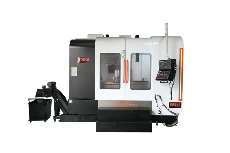
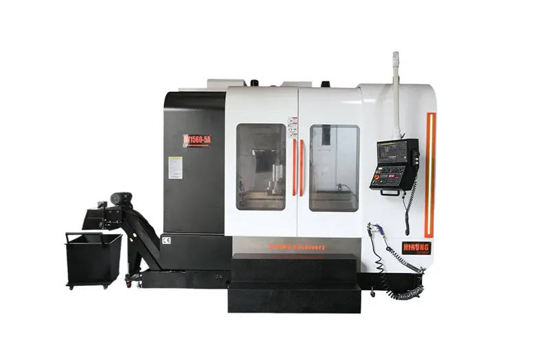
For large and heavy parts, the DV Series 5 axis machining center combines the spindle and the B-axis into a single unit, which avoids the precision loss that repeated assembly of separate components can introduce. The B-axis uses a direct-drive built-in electric spindle with a circular optical ruler, an indexing range of ±110° and a published positioning accuracy of 0.0015°. The structure uses Meehanite FC30 castings aged for 90 days, the machine weighs 12,000 kg, and published figures for the DV1560-5A include X/Y/Z positioning of ≤0.01 mm and repeatability of ≤0.005 mm to VDI 3441, with B/C positioning of ±10 arc-seconds and repeatability of ±4 arc-seconds. Maximum table load is 900 kg on the DV1350-5A and 1,200 kg on the DV1560-5A.
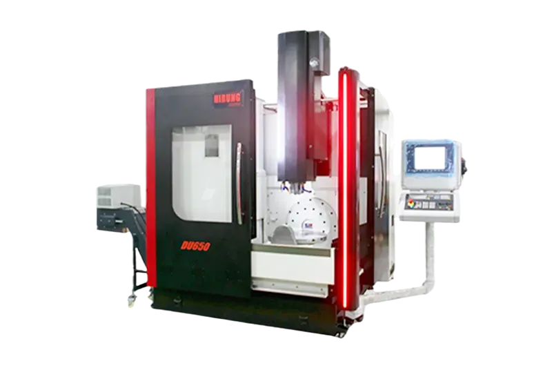
For smaller, high-precision components, the DU Series 5 axis universal machining center covers a different end of the range with HSK A63 spindles at 18,000 or 24,000 rpm. Published ISO 230-2 figures for the DU650 and DU1060 are ±0.005 mm positioning and ±0.002 mm repeatability on the linear axes, with 10 arc-seconds positioning and 5 arc-seconds repeatability on the B/C axes. The compact DU200 is published at 0.01 mm positioning and 0.005 mm repeatability, with 0.006° and 0.004° on the rotary axes.
When the part is too large for a trunnion table, or when the fixture and workpiece together exceed what a tilting table can carry, a gantry layout keeps the linear axes above the work. HIRUNG’s gantry-type 5 axis universal machining center pairs a rigid gantry structure with a direct-drive, double-supported B/C rotary table, and offers HEIDENHAIN or FAGOR linear scales as an option for applications where the feedback path matters as much as the drive path.
Which of these is right depends on the drawing, the material, the fixture and the production target — not on which has the larger number in the brochure.
Frequently Asked Questions
Does 5-axis machining always improve accuracy?
No. It improves accuracy where the dominant error source is datum transfer between setups. If your accuracy problem comes from machine rigidity, thermal growth, tool deflection or weak metrology, adding axes will not solve it and may make it worse, because the rotary axes contribute their own positioning error.
How much does 5-axis machining improve accuracy for complex parts?
There is no single figure, and any universal percentage should be treated with caution. The improvement is largest on relational tolerances between features that would otherwise be machined in different setups, and smallest on the size accuracy of an individual feature.
Is 3+2 indexed machining accurate enough for multi-face parts?
For prismatic parts whose faces are machined independently and where tolerances are referenced to a common datum, indexed 3+2 machining often delivers most of the benefit at lower cost and lower programming complexity. It is less suitable when surfaces must blend continuously, because each face is still machined with the tool axis fixed.
Why do features on different faces of my part not line up?
In most cases the cause is datum transfer rather than machine positioning. Each re-clamping and re-indicating step introduces a small difference, and those differences accumulate. Machining the part in one clamping, or reducing the number of setups, is usually the most direct fix.
What tolerance can a 5-axis CNC machining center hold?
It depends on the machine, the part size, the material, the tooling and the process. Published machine specifications describe positioning and repeatability of the machine axes under defined measurement standards, not the tolerance achievable on a production part. Judge capability with a representative test part measured to your own drawing.
Which matters more for accuracy: the machine or the CAM programming?
Both are necessary. A rigid, well-calibrated machine with a poor toolpath produces a poor part, and an excellent toolpath cannot compensate for a machine whose rotary axes are inaccurate. The machine sets the ceiling; the process determines how close you get to it.
How do I check 5-axis accuracy during machine acceptance?
Confirm the measurement standard behind the published figures, machine a representative test part rather than only a standard test piece, measure feature-to-feature relationships as well as individual dimensions, and repeat the measurement after a sustained run to check thermal drift.
Conclusion
5-axis machining improves accuracy for complex parts because it removes work, not because it adds motion. Fewer setups means fewer datum transfers, shorter tools mean less deflection, and a controlled tool axis means a more predictable cut on curved geometry. Equally, it does not compensate for a structure that lacks rigidity, a workshop that swings in temperature, a rotary axis that has not been calibrated, or a process that was never redesigned around single-setup machining.
The practical next step is to identify which of your parts lose accuracy to datum transfer today. Those are the parts where a 5-axis process pays back fastest, and they are also the parts worth using as an acceptance test piece. If you would like to review a drawing against the range, you can start with the CNC 5 axis machining center overview and send us the part geometry, material, fixture information and accuracy requirement.