Quick Answer: What Tolerance Can a 5 Axis CNC Machine Hold?
A 5 axis CNC machine does not have one tolerance figure. What it can hold depends on which tolerance you are asking about: size, position between features, profile of a curved surface, angle, or surface finish — and each of those is governed by a different part of the system.
That is why the question “what tolerance can it hold?” is the wrong starting point, and why suppliers who answer it with a single number are either simplifying or selling. The useful question is narrower: which tolerance on my drawing is hardest to hold, and what governs it?
In most high-precision work, the answer is not the size of a bore or the length of a step. It is the relationship between two features that sit on different faces, or the form of a surface that has to blend. Those are the tolerances that dominate scrap and that decide which machine configuration you need. The rest of this article turns each drawing callout into a machine requirement, so that a 5 axis machining center can be specified against the part rather than against a brochure.
Start With the Drawing, Not the Machine
Machine selection usually starts with travel, spindle speed and control brand. For tight-tolerance work that order should be reversed. The drawing tells you which capability you are paying for, and the table below maps the common callouts to what actually governs them.
| Tolerance type on the drawing | What it really depends on | Where it is usually lost | What to check on the machine |
|---|---|---|---|
| Linear size (a diameter, a length) | Process capability, tooling, thermal state | Tool wear, thermal growth, inconsistent finishing allowance | Repeatability, spindle cooling, tool measurement |
| Position / true position of a hole pattern | Axis positioning and datum consistency | Re-clamping between setups; no common datum | Linear axis positioning and repeatability, scale feedback |
| Coaxiality between features on different faces | Number of setups and rotary axis accuracy | Datum transfer; angular error amplified by distance | Rotary axis positioning and repeatability, drive type |
| Profile of a surface / free-form form tolerance | CAM strategy, machine dynamics, tool axis control | Ball-nose cusps, servo lag on direction changes, hand finishing | Simultaneous capability, servo tuning, control with tool-centre-point control |
| Angularity / angular tolerance | Rotary axis accuracy at the working radius | Angular error multiplied by distance from the rotary centre | Angular positioning in arc-seconds and the part radius |
| Surface finish (Ra) | Stepover, tool axis, tool condition, spindle | Cutting at the tool tip, long tool overhang, chatter | Spindle speed range and rigidity, tool holding interface |
| Runout / concentricity on turned or bored features | Spindle accuracy and workholding | Spindle error motion, chuck or fixture runout | Spindle specification, fixture design |
The pattern worth noticing: only one row in that table is governed mainly by machine positioning accuracy, and it is not the row most buyers worry about. Relational and angular tolerances are where a 5-axis configuration earns or loses its justification.
Translating Each Tolerance Callout Into a Machine Requirement
Size tolerances: capability, not specification
A machine with a published positioning accuracy of a few thousandths of a millimetre will not hold that on a production dimension, and it does not need to. Size is held by the process: a consistent finishing allowance, a known tool, controlled wear, and a stable thermal state. If your size tolerance is the problem, the fix is usually process control and in-process measurement, not a more expensive machine.
Positional and relational tolerances: where 5-axis earns its place
A hole pattern whose position is referenced to a datum on another face can only be held as well as the datum is preserved. Every time the part is unclamped and re-indicated, a small difference enters. Machining the whole part in one clamping turns a relational tolerance into a function of machine positioning instead of operator indicating — which is the single largest tolerance gain available on multi-face parts.
Profile and form tolerances on free-form surfaces
Form is a different discipline from position. A sculptured surface is cut by thousands of short moves, and the form tolerance is governed by how accurately the machine follows them: servo response, the control’s look-ahead, whether the tool axis can stay normal to the surface, and how the stepover is managed. A machine that positions accurately in a straight line can still produce a poor profile on a tight-radius curve if the servo tuning and the toolpath are not matched.
Angular tolerances: convert arc-seconds into millimetres
This is the calculation most buyers skip, and it is the one that most often explains a tolerance failure. Angular error is not a fixed length — it grows in proportion to the distance from the rotary axis centre. A few arc-seconds is negligible near the centre and significant at the edge of a large part.
| Distance from rotary centre | Effect of 10 arc-seconds of angular positioning | Effect of 4 arc-seconds of angular repeatability |
|---|---|---|
| 100 mm | About 4.9 µm | About 1.9 µm |
| 200 mm | About 9.7 µm | About 3.9 µm |
| 300 mm | About 14.5 µm | About 5.8 µm |
| 500 mm | About 24.2 µm | About 9.7 µm |
These figures are simply the geometric conversion of an angular specification into a linear one at the stated radius; they are not machining results, and they exclude tooling, thermal and material effects. Their purpose is to show why the same rotary specification can be comfortable on a small bracket and marginal on a large housing. When you compare machines on angular accuracy, always convert the published arc-second figure into a linear error at your own part radius before deciding whether it is adequate.
Surface finish: toolpath, tool axis and spindle
Finish requirements are frequently the hidden driver of a 5-axis purchase, because a surface that cannot be cut cleanly has to be finished by hand — and hand finishing is itself a source of form error. Cutting with the flank of the tool rather than its tip, keeping the tool short, and holding a consistent stepover generally improve finish more than increasing spindle speed.
Tolerance Capability by Machining Mode
Axis count is a poor proxy for tolerance capability. The mode in which the axes are used matters more.
| Machining mode | What it holds well | Where it struggles | Typical fit |
|---|---|---|---|
| 3-axis, multiple setups | Size tolerances within a single setup | Anything relational across faces | Prismatic parts with loose relational tolerances |
| Indexed 3+2 positioning | Angular relationships and position between faces machined in one clamping | Continuous blended surfaces; cusp marks between indexed positions | Multi-face prismatic parts, angled holes and pockets |
| Simultaneous 5-axis | Form on free-form surfaces; continuous profiles; undercut flow geometry | Requires validated CAM and post-processor; more dependent on servo tuning | Impellers, blisks, moulds, medical and aerospace geometry |
| 5-axis with probing and scale feedback | Relational tolerances over long runs and across thermal cycles | Higher initial cost; requires a measurement routine to be worth it | Serial production where drift, not capability, causes scrap |
The practical consequence: if your tightest callout is a positional tolerance between two faces, indexed 3+2 positioning in a single clamping may be sufficient — and it is a different purchase from a full simultaneous package. If your tightest callout is the profile of a blended surface, indexed positioning will not meet it however accurate the machine is.
Machine Specifications, Ranked by Tolerance Impact
Specification sheets present every number with equal weight. They are not equal. The table below ranks the specifications by how much they affect the tolerances that most often cause scrap.
| Specification | Which tolerance it governs | What to ask |
|---|---|---|
| Rotary axis angular positioning and repeatability | Angularity, coaxiality, any feature located away from the rotary centre | Figure in arc-seconds, the measurement standard, and the drive type |
| Rotary drive and feedback | Angularity and repeatability over time | Direct drive or worm gear; is there an independent angular encoder? |
| Linear axis scale feedback | Positional tolerances, especially over long runs and thermal cycles | Are linear scales standard or optional, on which axes, which brand? |
| Thermal management | Size and position drift across a shift | Spindle cooling type, cabinet cooling, warm-up procedure, compensation |
| Structure and guideways | Form and finish under changing cutting load | Casting material and stabilisation, roller or ball guides, machine weight |
| Spindle and tool interface | Finish, runout, size consistency | Taper, speed and torque curve, tool holding interface |
| Control and servo tuning | Profile on complex geometry | Control model, look-ahead, simultaneous capability, tool-centre-point control |
| Probing and tool measurement | Drift correction and setup consistency | Touch probe and tool setter: included, optional, or absent? |
Note the top two rows. On a 3-axis machine the rotary axes do not exist, so they cannot contribute error. On a 5-axis machine they are usually the dominant term in any tolerance that is measured away from the centre of rotation — which is why a 5-axis machine is not automatically more accurate than a 3-axis one on every feature.
The Three Limits That Are Not on the Machine
Even a well-specified machine will not hold a tolerance that the surrounding system cannot support.
Thermal growth across a shift
Spindle growth, ball-screw expansion and changing coolant temperature move the cutting point relative to the workpiece. The effect is small in the first hour and larger by hour six. Warm-up routines, spindle cooling and, where the tolerance justifies it, scale feedback and compensation are the controls — not a more accurate machine.
Tool deflection and tool holding
A slender tool reaching into a deep cavity deflects, and the deflection changes as the tool wears. In many applications the resulting error exceeds the machine’s own positioning error several times over. Shorter tools — which 5-axis positioning makes possible — are often the more effective correction.
Measurement uncertainty
A tolerance cannot be controlled with a measuring system that is not meaningfully finer than the tolerance itself. This is the reason metrology practice commonly applies a ratio between the measurement resolution and the tolerance band rather than treating an inspection reading as absolute. Before blaming the machine, confirm that the measurement method can actually resolve the difference you are arguing about.
How to State Tolerance Requirements in an RFQ
Most inaccurate quotations are caused by incomplete requirements, not by careless suppliers. The table below shows the information that changes a machine specification.
| What to state | Why it changes the quote | Example wording |
|---|---|---|
| The two or three callouts that actually cause scrap | Lets the supplier size the accuracy package instead of over-specifying everything | “Coaxiality 0.02 mm between the bore on face A and the bore on face D” |
| The datum structure | Determines whether single-setup machining is required | “Datum A is the machined face; the pattern is referenced to A and B” |
| Part radius from the intended rotary centre | Converts the angular requirement into a meaningful linear figure | “Critical features sit up to 280 mm from the centre of rotation” |
| Material and hardness | Drives spindle torque, tooling and deflection behaviour | “17-4PH, solution treated, machined in the hardened condition” |
| Batch size and run length | Decides whether drift control and probing are worth specifying | “80 parts per month, runs of 10, unattended finishing cycles” |
| Measurement method and available equipment | Determines whether the tolerance can be verified at all | “Verified on a CMM; in-process probing not currently available” |
| General tolerance standard on the drawing | Prevents disagreement about unspecified dimensions | “Unspecified dimensions to the general tolerance class noted on the title block” |
Capability vs. One-Off Inspection: How Acceptance Should Be Written
Why a single good part proves nothing
A supplier can produce one conforming part on almost any machine with careful setup and measurement. That demonstrates the operator, not the process. What you need to know is whether the machine holds the tolerance across a run, after warm-up, with tool wear, and on a Monday morning as well as a Friday afternoon.
A practical acceptance structure
Rather than “machine one part and measure it”, structure acceptance around a small capability exercise:
- Agree the critical callouts in advance — the two or three tolerances that matter, with the measurement method and who performs it.
- Machine a short run, not a single part — enough pieces to see spread rather than a single data point.
- Include a warm-up condition — measure after the machine has reached its normal running temperature, not from cold.
- Repeat after a deliberate interruption — a stop, a tool change and a restart will reveal whether the process is stable or dependent on a particular setup.
- Record the results as a range, not a pass/fail — the spread tells you how much of the tolerance band the process is consuming.
This takes longer than accepting one part, and it is the only version of acceptance that predicts what will happen after the machine is paid for.
Common Misconceptions About 5-Axis Tolerance
| Common belief | What is actually true | What to do instead |
|---|---|---|
| “A 5-axis machine is more accurate than a 3-axis machine” | It is more accurate at relational tolerances; it adds rotary error to everything else | Judge each tolerance type separately |
| “Published positioning accuracy equals the tolerance I can hold” | Positioning is measured on the machine, not on a part, under defined standards | Use a capability run on your own geometry |
| “Tighter machine specs give tighter parts” | Process, thermal state and tooling usually dominate | Fix the process before upgrading the machine |
| “Angular accuracy is a fixed number” | Its linear effect scales with distance from the rotary centre | Convert arc-seconds at your part radius |
| “Simultaneous 5-axis always gives a better finish” | Finish depends on tool axis, stepover and tool condition | Match the machining mode to the surface requirement |
| “If it measures good on the CMM, the machine is fine” | A CMM reading includes measurement uncertainty and says nothing about spread over a run | Measure a run, not a part |
How to Evaluate a Supplier on Tolerance Capability
These questions distinguish a supplier who can discuss tolerance from one who can only quote a specification sheet:
- Which measurement standard were your accuracy figures taken to, and can I see the report?
- What is the angular positioning figure, and what does it convert to at my part radius?
- Are linear scales and angular feedback included, optional, or unavailable on the model you are quoting?
- How is the machine compensated for thermal growth, and what warm-up procedure do you recommend?
- Will you run a short capability exercise on our part and share the spread, not just a pass/fail?
- Who validates the post-processor and the toolpath for the surfaces we need to hold?
- What is included in installation and commissioning, and who pays for the acceptance parts?
Where HIRUNG 5 Axis Machining Centers Fit
The reason to start from the tolerance rather than the machine is that the three HIRUNG 5-axis platforms are aimed at different tolerance problems, and the right one depends on which row of the first table governs your part.
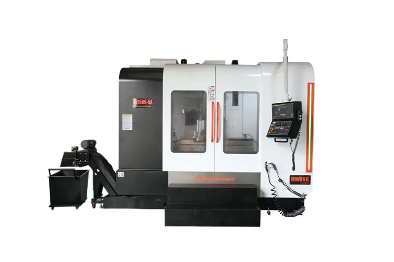
The DV Series 5 axis machining center is built for large and heavy parts where angular error at radius is the governing term. The spindle and the B-axis are built as a single unit rather than assembled from separate components, which avoids the precision loss that repeated assembly can introduce. The B-axis is a direct-drive built-in electric spindle with a circular optical ruler, ±110° of indexing and a published positioning accuracy of 0.0015°. Published VDI 3441 figures for the DV1560-5A are X/Y/Z positioning of ≤0.01 mm with repeatability of ≤0.005 mm, and B/C positioning of ±10 arc-seconds with repeatability of ±4 arc-seconds. Converting those angular figures gives roughly 14.5 µm of positional effect and 5.8 µm of repeatability effect at a 300 mm radius, and about half that at 150 mm. The structure is Meehanite FC30 aged for 90 days and weighs 12,000 kg, which supports the form and finish rows of the table as much as the positioning ones.
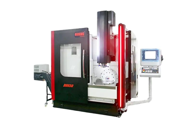
The DU Series 5 axis universal machining center covers smaller and medium components where part radius is modest and surface quality is often the governing requirement. Spindles are HSK A63 at 18,000 or 24,000 rpm, and the widened base separates the X/Y/Z axes from the B/C axes to keep moving mass low. Published ISO 230-2 figures for the DU650 and DU1060 are ±0.005 mm positioning and ±0.002 mm repeatability on the linear axes, with 10 arc-seconds positioning and 5 arc-seconds repeatability on B/C — which converts to roughly 4.9 µm and 2.4 µm respectively at a 100 mm radius. The compact DU200 is published at 0.01 mm positioning and 0.005 mm repeatability, with 0.006° and 0.004° on the rotary axes.
When the governing constraint is neither axis accuracy nor surface finish but simply that the part and its fixture exceed what a tilting table can carry, the specification question changes. A gantry-type 5 axis universal machining center pairs a rigid gantry structure with a direct-drive, double-supported B/C rotary table, and offers HEIDENHAIN or FAGOR linear scales as an option — relevant when the tolerance is held over long cycles and the feedback path matters as much as the drive path.
All three still depend on the process around them. A tolerance is held by the machine, the tooling, the CAM strategy, the thermal condition and the measurement method together, and no specification sheet substitutes for a capability run on the actual part.
Frequently Asked Questions
What tolerance can a 5 axis CNC machine hold?
It depends on the tolerance type. Size tolerances are governed mainly by process control and tooling; relational and angular tolerances are governed by datum consistency and rotary axis accuracy; form tolerances on curved surfaces are governed by CAM strategy and machine dynamics. There is no single figure that covers all three.
Is a 5 axis CNC machine more accurate than a 3 axis machine?
For tolerances between features on different faces, usually yes, because the part can be machined in one clamping. For a single dimension machined in one setup, not necessarily — a 5-axis machine adds two rotary axes whose error contributes to every feature positioned away from the centre of rotation.
How do I convert 5 axis angular accuracy into a linear tolerance?
Multiply the angular error by the distance from the rotary axis centre. As a worked example using a published B/C positioning figure of 10 arc-seconds, the linear effect is about 4.9 µm at a 100 mm radius, about 14.5 µm at 300 mm and about 24.2 µm at 500 mm. Always use your own part radius.
Do I need simultaneous 5-axis machining to hold tight tolerances?
Only if the tight callout is on a blended or continuous surface. For prismatic parts whose faces are machined independently, indexed 3+2 positioning in a single clamping often holds the relational tolerances that matter at a lower cost and with simpler programming.
Why does my part hold tolerance on the first piece but not across the batch?
The usual causes are thermal drift, tool wear and inconsistent setup rather than machine capability. Measure a run instead of a part, check warm-up procedure, and consider in-process probing if the drift is systematic.
Does adding linear scales improve the tolerance I can hold?
It can, particularly for positional tolerances held over long runs or across temperature changes, because scale feedback removes ball-screw thermal expansion from the position loop. Whether it is worthwhile depends on the tolerance and the cycle length, not on the machine size.
What should I include in an RFQ for a high precision 5 axis machine?
The two or three callouts that actually cause scrap, the datum structure, the maximum radius from the intended centre of rotation, material and hardness, batch size and run length, the measurement method available, and the general tolerance standard shown on the drawing.
How should a 5 axis machine acceptance test be written?
Agree the critical callouts and measurement method in advance, machine a short run rather than a single part, measure after warm-up, include a deliberate stop and restart, and record the spread across the run rather than a simple pass or fail.
Conclusion
Choosing a 5 axis CNC machine for high precision parts is a translation exercise. Take the tolerance that actually causes scrap, identify what governs it, and specify the machine against that — not against travel, spindle speed or axis count. Relational tolerances point to single-setup capability and rotary accuracy; angular tolerances point to arc-second figures converted at your own part radius; form and finish point to simultaneous motion, tool axis control and rigidity.
The next step is the same one that produces an accurate quotation: identify your two or three governing callouts, note the datum structure and the maximum radius from the centre of rotation, and send them with the drawing. You can start with the CNC 5 axis machining center range, or send the part geometry, material, fixture information and tolerance requirement for a configuration review.