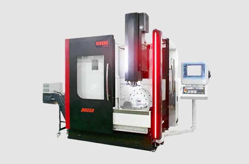
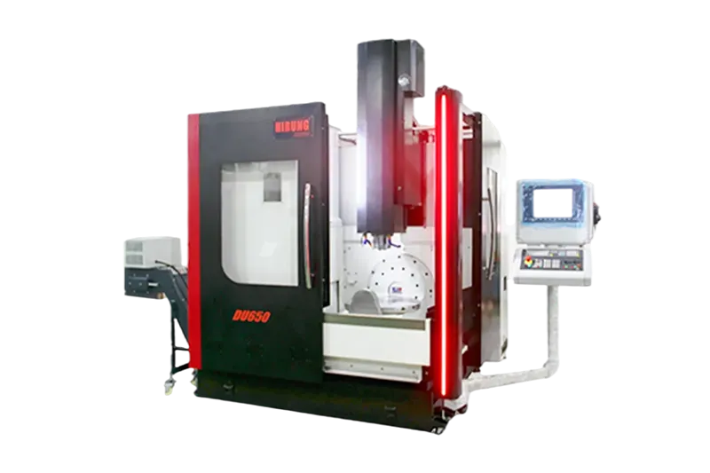
Choosing between a trunnion table and a swivel head determines the kinematic reach, cutting rigidity, and physical boundary limits of your five-axis manufacturing operations. The direct answer comes down to workpiece mass, envelope geometry, and tool access requirements: trunnion tables (table-table kinematics) provide superior undercut clearance and dynamic control for compact to medium multi-sided parts, while swivel-head configurations (head-head or head-table kinematics) are required for massive, oversized components where rotating the raw stock would induce excessive inertia, deflection, or mechanical interference.
For shop managers, process planners, and procurement engineers, selecting an incompatible configuration leads to compromised tolerances, spindle housing collisions, or total inability to support workpiece payload. When evaluating modern 5-axis CNC machining, matching your part geometry directly to axis kinematic behavior prevents costly workholding workarounds and preserves surface finish integrity across continuous contours.
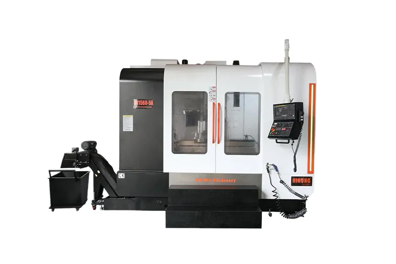
Trunnion vs. Swivel Head: Understanding the Kinematic Difference
The primary mechanical differentiator between these machine architectures lies in which side of the cutting equation executes the rotary and tilting movements: the workpiece or the spindle.
| Kinematic Attribute | Trunnion Table (Table-Table) | Swivel Head (Head-Head) |
| Spindle Architecture | Fixed-orientation spindle (Pure $X, Y, Z$ linear motion) | Articulating spindle head (Houses $B/A$ rotary tilt joints) |
| Workpiece Motion | Workpiece tilts and rotates ($A/B + C$ rotary axes) | Workpiece remains stationary relative to angular tilt |
| Mechanical Pivot Location | Dual-supported trunnion cradle on machine table | Internal rotary drive joints inside the spindle housing |
| Cutting Tool Vector | Tool maintains constant vertical alignment with machine column | Tool angle articulates dynamically around the part geometry |
| Machine Base Role | Carries dynamic rotational loads and tilting moments | Supports static gravitational weight on a rigid, flat bed |
How Rotary Axis Placement Changes the Machining Dynamic
In a trunnion table machine (commonly configured with A- and C-axes or B- and C-axes on the table), the cutting spindle operates solely in linear tool movements (X, Y, and Z). The raw billet or casting mounts directly to a rotary platter supported by a dual-sided trunnion cradle. Tilting and indexing occur entirely on the workpiece side. This keeps the spindle nose rigidly aligned with the machine column, isolating the tool assembly from angular deflection forces.
In a swivel-head machine (incorporating either an articulating head-head setup or a hybrid head-table design), the spindle housing contains the tilting pivot (often a B-axis) or compound rotational joints (A/C-axes). The workpiece sits on a stationary bed or a standard rotary table that controls only one axis of rotation. Because the spindle tilts toward the workpiece, the machine bed supports purely vertical, downward gravitational forces from the raw material without tilting it off-center.
These divergent mechanical paths create specific boundaries regarding allowable part weight, vibration dampening, and tool-to-workpiece approach angles.
Part Size and Weight: Where the Boundary Lies
Workpiece mass and volumetric envelope serve as the earliest filtering criteria when determining machine kinematics.
Trunnion Limits: Dynamic Balance and Rotary Table Payload
A trunnion assembly operates as an oscillating lever arm. When a raw billet or forging sits clamped to the platter, tilting the A-axis shifts the center of gravity away from the pivot centerline:
- Rotary Inertia: Accelerating and decelerating an off-center workpiece demands high torque from direct-drive or worm-gear rotary drives. As part mass increases, dynamic backlash and reversal spikes degrade contouring accuracy.
- Payload Thresholds: Trunnion tables are structurally limited by platter bearings and drive gear capacities. Exceeding recommended weight limits accelerates mechanical wear on worm drives and causes servo hunting during simultaneous five-axis contours.
- Swing Clearance: Long, slender parts swinging through the trunnion cradle sweep a wide circular path, creating acute collision zones against machine way covers and enclosure walls.
Swivel Head Strengths: Stationary Heavy Workpieces and Large Castings
Swivel-head machines eliminate rotational inertia on the workpiece side:
- Static Load Support: The machine table rests directly on the base casting or foundation. This design supports heavy structural components, thick alloy dies, and massive turbine forgings weighing thousands of kilograms without taxing rotational drives.
- Floor-Space Efficiency for Long Parts: For lengthy structural beams (such as aerospace wing spars or lengthy tie rods), the part remains flat along an extended X-axis bed, allowing the articulating head to sweep across features from above and from side angles.
Workpiece Envelope and Configuration Suitability Matrix
| Workpiece Characteristic | Recommended Kinematic Setup | Primary Engineering Rationale |
| Heavy Castings & Forgings | Swivel Head / Head-Table | Table supports massive static loads without dynamic rotational deflection. |
| Compact Prismatic Blocks | Trunnion Table (Table-Table) | Rigid fixed spindle nose permits high material removal rates on multiple faces. |
| Long Structural Beams | Swivel Head (Head-Head) | Avoids clearance swing collisions inside the machine enclosure along the X-axis. |
| Thin-Walled Impellers & Blisks | Trunnion Table (Table-Table) | Deep undercut angles accessible with short, rigid milling cutters. |
| Large Mold Bases & Cavities | Swivel Head / Hybrid | Spindle reaches deep cavity walls while heavy blocks rest firmly on the bed. |
Tool Access and Collision Risks: Undercuts, Deep Cavities, and Impellers
Tool clearance determines not only whether a part is machinable, but also how short and rigid the cutting tool can be during cycle runtime.
| Tool Access Criterion | Trunnion Table Setup | Swivel Head Setup |
| Kinematic Approach | Tool approaches vertically; part rotates and tilts to present surfaces | Spindle body articulates and angles toward stationary geometry |
| Reverse Tapers & Undercuts | Exceptional reach; cradle easily clears angles past 90° (+120° / -30°) | Limited by spindle head pivot arc and physical head dimensions |
| Tool Assembly Overhang | Minimal overhang; short standard tools maintain high cutter rigidity | Often requires extended tool holders to reach past bulky head housing |
| Primary Interference Zone | Part perimeter swinging into machine frame or table wall enclosures | Spindle nose and motor casing contacting sidewalls or tall fixtures |
Trunnion Table for Compact, Multi-Sided Precision Features
Trunnion setups excel when machining features that wrap entirely around a part or require negative drafts:
- Negative Draft and Undercut Machining: Trunnion cradles typically tilt past 90 degrees (often up to +120° / -30° or more depending on manufacturer specs). This allows standard end mills to reach reverse-taper angles and undercut profiles without relying on custom-ground form tools or long side-milling arbors.
- Shorter Tool Overhang: Because the part tilts toward a stationary vertical spindle, the cutter can remain short and stubby. Minimizing tool overhang reduces tool deflection ($y \propto L^3$), eliminating chatter and delivering superior Ra surface finishes on turbine blades, complex prosthetic joints, and centrifugal impellers.
Swivel Head for Deep Pocketing and Minimal Tool Deflection
Swivel heads provide distinct kinematic benefits for large-scale cavities and deep molds, but introduce spindle housing clearance considerations:
- Deep Cavity Profiling: An articulating head tilts the tool shank into deep structural cavities, keeping the cutter perpendicular or at a designated lead angle relative to the drafted sidewall.
- Spindle Housing Interference: The primary trade-off of a swivel head is the physical footprint of the milling head itself. The housing contains high-torque motors, drive joints, and cooling lines. When tilting into deep pockets or close to upright clamps, the bulky spindle nose can interfere with the part wall long before the cutter reaches the programmed depth.
Cutting Rigidity and Accuracy: Heavy Milling vs. High-Speed Finishing
Dynamic stability under cutting load dictates surface accuracy, cycle efficiency, and insert life. Both architectures balance structural stiffness differently across varying operational regimes.
Torque Transmission and Structural Damping Under Heavy Loads
A fixed spindle on a trunnion machine sits bolted to a massive vertical column or bridge casting. This setup provides continuous damping against heavy Z-axis plunge loads and aggressive X/Y roughing passes. When roughing tough materials like titanium, Inconel, or hardened tool steels, the machine structure absorbs radial and axial cutting loads with minimal joint deflection.
Conversely, a swivel head relies on mechanical or direct-drive rotary joints inside the head housing. Under heavy roughing cuts, torsional forces push directly against these rotary axes. While modern configurations utilize high-clamping-force pneumatic or hydraulic brakes to lock the rotary axis during 3+2 positional cutting, simultaneous 5-axis continuous roughing exposes the joint mechanisms to cutting force vectors that can provoke harmonic vibration if feeds and speeds are not properly balanced.
Thermal Stability and Dynamic Precision Control
- Trunnion Thermal Behavior: The spindle generates heat, but its growth occurs predictably along a linear Z-axis path, easily compensated for by standard thermal probes and encoder maps. However, dual-drive trunnion tables must contend with thermal expansion across the cradle pivot line to avoid center-of-rotation drift.
- Swivel Head Kinematic Error Stacking: Every degree of angular error at the pivot head projects over the length of the tool gauge line. A minute thermal expansion or micro-backlash deviation at the B-axis pivot magnifies linearly at the tool tip. Utilizing closed-loop direct optical encoders and calibrated kinematic compensation routines (such as RTCP/TCPM) is essential to preserve micro-level tolerances.
For manufacturers requiring high geometric consistency across tight-tolerance surfaces, utilizing an experienced partner with calibrated precision 5-axis CNC machining services ensures proper machine kinematic tuning and tool vector compensation before chips begin to fly.
Engineering Decision Framework: Selecting the Right 5-Axis Setup
To select the proper configuration, engineering teams should follow this sequential 4-step evaluation:
| Evaluation Phase | Check Item | Decision Indicator | Actionable Configuration Choice |
| Phase 1: Payload Limits | Combined weight of billet + fixture | Exceeds dynamic rotary platter rating | Select Swivel Head (Static bed absorbs load) |
| Phase 2: Workpiece Envelope | Diagonal rotational sweep radius | Risk of collision with machine guards/stroke | Select Swivel Head (Part remains stationary) |
| Phase 3: Geometric Undercuts | Continuous negative draft $>90^\circ$ | High multi-sided undercut accessibility | Select Trunnion Table (Tilting cradle clears draft) |
| Phase 4: Tool Length & Finish | Cavity depth vs. tool gauge length | Priority on minimal tool deflection / low Ra | Select Trunnion Table (Uses shortest cutter) |
Step 1: Evaluate Part Mass Against Dynamic Payload Limits
Confirm the total weight of the raw workpiece plus clamping fixtures. If the combined mass approaches or exceeds the machine’s dynamic table load specification, choose a swivel head. Forcing a heavy component onto a trunnion table causes servo lag, contour errors, and premature drive wear.
Step 2: Calculate Rotational Swing Clearance
Determine the diagonal boundary (maximum rotational swing) of the raw stock. If tilting the part sweeps beyond the machine’s X/Y/Z physical stroke or risks colliding with the column walls, the part must remain stationary on a swivel-head machine.
Step 3: Map Tool Access Paths and Undercuts
Inspect CAD model surfaces for reverse tapers, complex 5-sided prismatic features, or continuous organic surfaces (such as turbomachinery blades). If the cutter must access undercut angles exceeding 90 degrees relative to the setup plane, a trunnion table delivers direct clearance without tool collision.
Step 4: Prioritize Rigidity vs. Housing Clearance
Evaluate required cutter length. If the geometry permits short, rigid cutters that maximize surface smoothness and minimize vibration, a trunnion provides optimal performance. If the part features tall, vertical exterior walls or deep narrow die cavities, verify that the swivel-head spindle casing will not interfere with raw stock boundaries before committing to the setup.
Quick Reference: Trunnion vs. Swivel Head Feature Comparison
Review the essential engineering trade-offs between both architectures in this reference matrix:
| Evaluation Criteria | Trunnion Table (Table-Table) | Swivel Head (Head-Head / Head-Table) |
| Primary Motion Mechanism | Part tilts and rotates; spindle moves linearly ($X, Y, Z$) | Spindle articulates/tilts; part remains stationary or rotates on flat bed |
| Max Workpiece Capacity | Limited by table payload and rotational inertia | Significantly higher; limited only by bed structural weight capacity |
| Optimal Workpiece Envelope | Compact to medium cubic/cylindrical parts | Large, long, flat, or extremely tall industrial components |
| Tool Overhang & Rigidity | Short tool lengths possible; high rigidity at the tool tip | Requires longer tools for certain cavity walls; spindle body clearance check required |
| Undercut Machining Range | Exceptional; cradle typically tilts past 90° (+120° / -30°) | Moderate; constrained by head articulation range and body interference |
| Roughing Dynamics | High damping on spindle column; table drives require conservative feeds on heavy stock | Robust bed damping; head pivot joints require robust locking brakes during heavy cuts |
| Typical Target Parts | Impellers, bone plates, valves, aerospace brackets, small housings | Aircraft structural bulkheads, automotive stamping dies, energy turbine casings |
Frequently Asked Questions About 5-Axis Configurations
Can a trunnion table handle 5-axis machining for aerospace structural ribs?
It depends strictly on the rib length. Small to medium aerospace brackets and structural fittings under 500–800 mm fit well on a trunnion table, benefiting from short tool setups and rigid multi-sided access. However, long structural spar sections and large monolithic bulkheads typically exceed trunnion swing envelopes, requiring long-bed swivel-head machines.
Why are large mold cores typically machined on swivel-head centers?
Large injection molds and stamping dies often start as heavy rectangular alloy steel blocks weighing several tons. Placing this mass on a tilting table is mechanically unfeasible due to dynamic imbalance. A swivel-head center allows the massive block to remain stationary on the floor bed while the articulating spindle reaches deep draft angles and core contours from multiple sides.
Does a swivel-head configuration suffer from thermal expansion at the pivot?
All multi-axis systems encounter thermal drift, but swivel heads require specialized kinematic monitoring. Because the pivot point sits upstream of the tool tip, minute thermal expansions within the spindle head bearings or pivot joints can cause angular deviations that amplify along the tool length. High-precision machines resolve this with continuous internal chiller loops, direct-measuring rotary scales, and dynamic thermal calibration cycles.
Optimize Your 5-Axis Production with HIRUNG
Configuring the ideal machining strategy requires matching production tolerances, cycle times, and part geometries with the correct kinematic setup. Whether your project involves intricate turbine components requiring the tight tool rigidity of a trunnion setup, or heavy industrial housings demanding large-bed stability, our manufacturing engineers evaluate your drawings to ensure efficient toolpath clearance and structural accuracy.
To verify kinematic feasibility, optimize cycle times, or request a technical quote, explore our complete custom 5-axis CNC capabilities or submit your 3D CAD models directly to our technical engineering team for an in-depth manufacturability evaluation.
Key Takeaways
- Core Kinematic Split: Trunnion tables rotate and tilt the workpiece beneath a stationary spindle; swivel heads articulate the spindle tool vector over a stationary or single-axis rotating table.
- Workpiece Boundaries: Trunnion tables are constrained by rotational payload capacity and swing interference, making them ideal for compact to medium parts. Swivel heads accommodate large, heavy, and structurally extended components.
- Tool Rigidity: Trunnion setups generally allow shorter tool overhang, reducing chatter and delivering high surface finishes on complex, multi-sided geometries.
- Collision Zones: Swivel-head configurations must be evaluated for spindle housing clearance when machining deep internal pockets or working near tall fixtures.
- Process Selection: Use a 4-step decision sequence (Weight $\rightarrow$ Envelope $\rightarrow$ Undercut Access $\rightarrow$ Tool Rigidity) to select the correct machine setup before manufacturing begins.
FAQ
Q1: What is the main difference between trunnion table and swivel head 5-axis machines?
A1: A trunnion table moves the workpiece along two rotary axes while the cutting spindle moves purely linearly. A swivel-head machine houses at least one or both rotary axes inside the articulating spindle head, keeping the workpiece stationary or rotating it on a flat bed.
Q2: Which 5-axis configuration is best for heavy metal parts?
A2: Swivel-head configurations are best suited for heavy parts. Because the workpiece remains anchored to a stationary bed, machine axes do not suffer from the rotational inertia and weight constraints inherent to tilting trunnion cradles.
Q3: Can trunnion tables achieve better surface finishes than swivel heads?
A3: On small to medium complex geometries, trunnion tables often deliver superior surface finishes because the part tilts directly toward a short, rigid spindle tool, minimizing tool overhang and cutting chatter.
Q4: What causes collisions on swivel-head 5-axis machines?
A4: Collisions on swivel-head machines typically occur when the bulky outer casing of the articulating spindle housing makes contact with tall fixtures, sidewalls, or the raw billet while attempting to reach steep draft angles in deep pockets.
Q5: What is a hybrid head-table 5-axis configuration?
A5: A hybrid (or head-table) machine splits the rotary axes: one rotary axis is built into the articulating spindle head (such as a B-axis tilt), while the second rotary axis sits on the machine bed (such as a C-axis rotary table).