Evaluating 5-axis machining center specifications requires looking past nominal marketing figures to analyze the mechanical and kinematic realities of your workpiece. The true performance of an industrial 5-axis CNC machine depends on seven interdependent factors: kinematic configuration, spindle torque-to-speed dynamics, volumetric positioning accuracy, controller block processing capability, machine base damping, active thermal stability, and tool changer ergonomics.
Misjudging these parameters often leads to excessive vibration, thermal drift during long cycles, or poor surface finishes on complex 3D contours. This guide outlines how manufacturing engineers, machine shop managers, and procurement teams should audit technical parameter sheets to select an industrial machining center that matches their specific production demands.
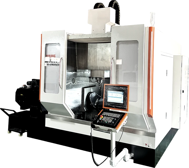
Spec #1: Kinematic Architecture – Trunnion Table vs. Swivel Head Limitations
The kinematic layout dictates tool access, interference zones, and the dynamic mass distribution of your setup. The two dominant kinematic configurations in modern 5-axis CNC machining are the trunnion table design (table-table) and the swivel head design (head-head or head-table).
| Architecture Level | Trunnion Table (Table-Table) | Swivel Head (Head-Table / Head-Head) |
| Spindle Assembly | Fixed Spindle Housing (Translational $Z$-axis movement only) | Articulating Milling Head (Pivots along $B$ and/or $A$ axes) |
| Tool Tip Dynamics | Rigid, constant vertical orientation; minimal cantilever droop | Tool vector dynamically tilts; requires continuous spatial vector tracking |
| Workpiece Position | Clamped to tilting cradle; reoriented across compound angles | Mounted to stationary bed or flat rotary table (horizontal $C$-axis) |
| Table & Inertia Profile | Tilting / Rotating Table: Rotary drive constantly moves workpiece mass | Stationary / Rotary Bed: Constant workpiece mass inertia throughout cycle |
Rotary Axis Envelope and Undercut Clearance
In a trunnion table setup (typically A-axis tilt with a C-axis rotary table), the entire component tilts. This arrangement allows superior clearance for compact parts and deep 5-sided pocketing because the spindle housing remains fixed vertically.
However, evaluate the tilting range carefully:
- Standard trunnions often tilt from -120° to +30° or -110° to +110°.
- If your components require negative undercuts or continuous complex impellers, verify that the tilt envelope does not cause mechanical interference between the table cradle and the spindle nose housing.
Table Load Dynamics vs. Constant Inertia
In trunnion configurations, the rotary drive motors must constantly accelerate the combined weight of the table, workholding, and raw stock:
- Heavy, asymmetric workpieces create significant inertial lag and can introduce backlash or servo oscillation during continuous 5-axis contouring.
- For components exceeding 800 to 1,000 kg, swivel head configurations—where the rotary axes are located in the milling head—keep the table stationary or strictly rotary along the Z-axis (C-axis). This ensures consistent mass inertia regardless of raw material weight.
| Kinematic Type | Typical Part Size & Weight Profile | Primary Strengths | Inherent Limitations |
| Trunnion Table (Table-Table) | Small to medium parts; typically under 800 kg | High overall rigidity; fixed spindle eliminates geometric head-droop; ideal for 5-sided prismatic parts | Part weight directly impacts rotary axis dynamic response; clearance constraints with long tooling |
| Swivel Head (Head-Table / Head-Head) | Large, heavy components; structural plates | Workpiece mass does not affect machine dynamics; easier crane loading; handles long workpieces | Articulating head introduces additional mechanical joints; thermal expansion in the head requires rigorous compensation |
Spec #2: Spindle Performance Curve – Balancing Torque, Speed, and Tool Interface
Evaluating a spindle solely by its maximum RPM is a critical error. The spindle’s power-to-torque curve determines whether a machine can handle heavy roughing passes in tough alloys or is restricted entirely to light-load, high-speed finishing.
| Operating Regime | Speed Range (RPM) | Mechanical Power & Torque Output | Typical Cutting Application |
| Constant Torque Zone | $0 \text{ RPM} \rightarrow \text{Base RPM}$ | Constant peak torque; power increases linearly with speed | Heavy hogging, face milling in titanium, nickel alloys, and tool steels |
| Base RPM Threshold | Intermediate transition point | Peak continuous power rating achieved ($100\%$ duty cycle mark) | Optimal transition speed balancing feed rate and chip load |
| Constant Power Zone | $\text{Base RPM} \rightarrow \text{Max RPM}$ | Constant maximum power output; torque declines inversely with speed | High-speed surface contouring, micro-milling, and aluminum finishing |
Analyzing the Power-to-Torque Curve
Look for the base RPM—the threshold speed where the spindle reaches its maximum rated power. Below this base RPM, the spindle operates in the constant-torque zone; above it, torque declines as RPM increases.
- Aluminum and non-ferrous alloys: Require high peripheral cutting speeds ($15,000$ to $24,000+$ RPM). Here, low-end torque is secondary to high dynamic balancing and rapid acceleration/deceleration rates.
- Titanium, nickel alloys, and hardened tool steels: Demand substantial low-end torque at low cutting speeds ($1,500$ to $4,500$ RPM). If a $20,000$ RPM spindle delivers only $35\text{ Nm}$ of torque below $3,000$ RPM, high-feed roughing will stall the drive motor or induce chatter.
Tool Holder Interface: HSK vs. BT/BBT
The interface standard directly impacts rigidity under the combined radial and axial cutting loads inherent to 5-axis simultaneous motion:
- HSK (e.g., HSK-A63, HSK-A100): Features a 1:10 short taper with dual contact (flange face and taper) alongside an internal centrifugal clamping mechanism. As centrifugal force increases at high RPM, the collet expands outward, pulling the holder tighter against the spindle face. This provides superior radial runout control and z-axis repeatability under high-speed milling.
- Dual-Contact Steep Tapers (e.g., BBT40, BBT50): Provide face-and-taper contact using traditional drawbar mechanics. While excellent for heavy, low-RPM roughing, standard steep tapers without face contact risk taper expansion and fretting wear when operated under heavy side loads at high speeds.
Spec #3: Positioning Accuracy vs. Volumetric Dynamic Repeatability
Machine specification sheets often quote linear axis accuracy according to ISO 230-2 or VDI/DGQ 3441 standards. However, static unidirectional repeatability along an isolated X, Y, or Z travel rail does not represent the spatial precision of a simultaneous 5-axis toolpath.
Direct Feedback via Linear and Rotary Optical Scales
Standard indirect feedback calculates position via ballscrew pitch rotation and rotary motor encoders. Over long cycles, ballscrew pitch expansion from friction heat introduces uncorrected linear position errors.
- Industrial 5-axis machining demands absolute glass scales on all linear axes (with resolution down to sub-micron levels).
- Rotary axes (A, B, or C) must feature direct-drive angular encoders mounted directly on the center of rotation, rather than relying on motor shaft sensors positioned behind worm gears or planetary reduction sets.
True Volumetric Accuracy and Verification Standards
Volumetric positioning accounts for the cumulative geometric errors across all degrees of freedom, including pitch, yaw, roll, straightness, squareness, and radial runout.
When reviewing manufacturer accuracy specs, request confirmation of standardized multi-axis testing procedures:
- ISO 230-4 Ballbar Circularity Tests: Evaluates mechanical alignment and servo synchronization in simultaneous circular moves.
- NAS 979 Standardized Test Piece: An aerospace machining test standard where a circle-diamond-square specimen is cut using continuous five-axis contouring to verify dynamic contouring accuracy, corner transition overshoot, and surface blend tolerances under real cutting loads.
Spec #4: CNC Controller Capability – Block Processing Time, Look-Ahead, and RTCP
A 5-axis machine’s mechanical capability is constrained by its computer numerical control (CNC). High-speed continuous surface machining relies on thousands of microscopic point-to-point vector blocks generated by modern CAM systems.
| Controller Pipeline Stage | Core Technical Metric | Operational Impact on Machining Performance |
| 1. Look-Ahead Buffer | $\ge 600\text{ to }1,000+\text{ blocks}$ | Evaluates upcoming 3D curvature to plan dynamic acceleration/deceleration profiles without abrupt axis deceleration. |
| 2. Block Processing Time (BPT) | $\le 0.5\text{ to }1.0\text{ ms}$ | Interpolates micro-segments fast enough to eliminate axis hesitation, avoiding micro-dwell marks on sculpted surfaces. |
| 3. Real-Time Tool Center Point (RTCP) | Real-time coordinate kinematics | Continuously manages tool tip location relative to the workpiece, compensating for tool wear and rotational pivot offsets. |
Real-Time Tool Center Point Control (RTCP / TCPM)
Without native RTCP, the CAM post-processor must calculate physical machine pivot lengths in advance. If a cutter wears down or is re-ground to a different length, the operator must re-post the entire program.
RTCP allows the controller to maintain the exact position of the tool tip relative to the workpiece in real time, automatically compensating for tool wear, pivot length shifts, and part setup orientation across tilting axes.
Look-Ahead and Block Processing Times
- Block Processing Time (BPT): The controller must interpret micro-segments in less than $0.5\text{ to }1.0\text{ milliseconds}$. If the feed rate demands faster block execution than the CPU can compute, the machine will subtly hesitate at vector transitions, resulting in micro-dwell marks on finished part surfaces.
- Look-Ahead Buffer: Professional 5-axis controls require look-ahead buffers capable of reading $600\text{ to }1,000+$ blocks ahead. This allows the controller’s acceleration/deceleration algorithms to smooth velocity curves through complex corners without sacrificing feed rate.
Spec #5: Machine Base Rigidity and Damping Characteristics
Five-axis tool movements produce fluctuating side loads and rapid direction reversals that can shake a lightweight structure. The material composition of the machine base directly determines how effectively these mechanical vibrations are dampened before reaching the cutting zone.
Cast Iron vs. Mineral Casting (Polymer Concrete)
- High-Grade Meehanite Cast Iron: Remains the industry benchmark for standard cutting structures. It offers predictable mechanical strength, high torsional stiffness, and reliable resistance to deflection under heavy side-loading.
- Mineral Casting (Polymer Concrete): Blends quartz and granite aggregates with epoxy resin binders. It exhibits vibration-damping properties up to ten times superior to standard grey cast iron and features significantly lower thermal conductivity, insulating the machine base from ambient shop-floor temperature shifts.
Roller Linear Guideways vs. Ball Guides
For 5-axis centers handling demanding materials:
- Roller-type linear guideways use cylindrical rollers instead of spherical ball bearings.
- The contact zone changes from point-contact to line-contact. This line contact distributes structural load across a broader surface area, reducing structural deflection under dynamic cutting forces and extending guide life during heavy roughing.
Spec #6: Thermal Growth Management – Passive Design and Active Compensation
Thermal deviation causes more dimensional variation in precision parts than mechanical wear. A temperature shift of just $1^\circ\text{C}$ over a $1,000\text{ mm}$ steel ballscrew can result in roughly $11.5\text{ µm}$ of linear drift—often exceeding tight blueprint tolerances.
| Thermal Source | Engineering Mechanism | Function in Maintaining Volumetric Accuracy |
| Spindle Bearing & Motor Heat | Chilled Liquid Cooling Jacket | Continuously circulates coolant around stator and spindle housing to prevent axial spindle growth. |
| Friction at Ballscrew Nuts | Hollow-Cored Fluid Circulation | Extracts internal friction heat directly from the drive axis center, preserving ballscrew pitch integrity. |
| Shop-Floor Ambient Shifts | Algorithmic Structural Sensors | Multi-point temperature sensors feed real-time expansion offsets to the CNC control drives. |
Core Thermal Mitigation Engineering
When evaluating a 5-axis technical specification sheet, verify the presence of comprehensive thermal controls:
- Spindle Chiller Circulation: Temperature-controlled liquid coolant must circulate through an integrated jacket surrounding the spindle bearings and motor stator.
- Hollow-Cored, Internally Cooled Ballscrews: High-duty cycles generate heat at the ballscrew nut. Hollow-core fluid cooling extracts heat from the inside out, keeping the screw at a stable operating temperature.
- Symmetric Machine Design: Asymmetric casting designs expand unevenly when heated, tilting the spindle vector. Thermally balanced machine architecture ensures any minor expansion occurs symmetrically along axial baselines.
Algorithmic Multi-Point Compensation
Modern high-precision 5-axis machines integrate thermal sensors throughout the casting, spindle housing, and column. The CNC controller feeds this real-time temperature data into structural algorithms, applying dynamic vector offsets to the axis drives to cancel out physical thermal expansion.
Spec #7: Tool Changer Ergonomics and Automation Integration Interfaces
In a 5-axis environment, cycle efficiency is frequently compromised by inadequate tool capacity or sluggish tool exchanges. Complex geometry often requires standard end mills, ball mills, form tools, thread mills, drills, and inspection probes within a single setup.
ATC Capacity and Chip-to-Chip Speed
- Magazine Capacity: While a 30-tool carousel is common on 3-axis mills, industrial 5-axis machining centers typically require a minimum of $40\text{ to }60$ positions. This accommodates redundant tooling for uninterrupted shifts alongside the wide tool varieties required for multi-sided operations.
- Chip-to-Chip Time: Do not evaluate tool changes solely by the “Tool-to-Tool” metric (the mechanical movement time of the arm). Demand the “Chip-to-Chip” time per VDI 2852 standards. This measurement includes spindle deceleration, orientation, tool swapping, axis acceleration, and spindle spin-up back to cutting speed.
Zero-Point Clamping and Pallet Integration
To maximize spindle run time, evaluate the machine’s interface readiness for automated pallet changers (APC) or robotic tendering:
- Pneumatic and Hydraulic Rotary Pass-Throughs: Essential for actuating zero-point chucks and automated workholding clamps mounted on the tilting rotary table.
- Automated Pneumatic Door and Fieldbus Protocols: Integrated software protocols (such as OPC UA or Profinet) enable third-party automation cells to monitor machine status, manage door operations, and execute tool life management routines without complex retrofitting.
The 5-Axis Specification Scorecard: Pre-Purchase Evaluation Checklist
Use this structured scorecard to evaluate machine proposals against technical requirements before issuing a formal Request for Quotation (RFQ).
| Specification Area | Standard Inspection Item | Minimum Industrial Threshold | Critical Red Flags to Watch |
| 1. Kinematics | Table Tilt & Rotation Range | A: $-120^\circ \text{ to } +30^\circ$ (or better); C: $360^\circ$ continuous | Insufficient negative tilt angle causing fixture or spindle nose collisions |
| 2. Spindle | Torque Curve & Interface | HSK-A63 or BBT40; minimum $100\text{ Nm}$ torque (if machining titanium/steels) | High peak RPM matched with negligible low-end torque ($<40\text{ Nm}$) for heavy alloy work |
| 3. Feedback | Scales & Encoders | Direct absolute optical scales ($X/Y/Z$); direct rotary encoders on rotational axes | Rotary positioning derived solely from motor shaft encoders without direct table feedback |
| 4. Control | RTCP & Processing Speed | Native RTCP capability; Block Processing Time $\le 0.5\text{ ms}$; $\ge 1,000$ block look-ahead | Controller requires CAD/CAM post-processing for basic tool length offset compensation |
| 5. Rigidity | Base Construction & Guides | Heavy Meehanite cast iron or mineral casting; roller-type linear guideways | Thin fabricated sheet-welded beds; ball-type guideways applied on heavy-duty roughing platforms |
| 6. Thermal | Cooling & Compensation | Chilled liquid cooling jacket on spindle; active multi-point sensor compensation | Thermal compensation sold as a purely passive software timer without structural heat sensors |
| 7. Automation | Capacity & Interface | Minimum 40-tool ATC; standard hydraulic/pneumatic pass-throughs for zero-point fixtures | Standalone table with no internal lines for fluid/pneumatic supply, requiring external hose bundles |
Frequently Asked Questions
What level of positioning accuracy is realistic for general industrial parts on a 5-axis center?
For precision industrial, mold, and aerospace applications, an industrial-grade 5-axis machining center should achieve linear positioning accuracy within $\pm 0.003\text{ mm to }\pm 0.005\text{ mm}$ ($\pm 3\text{ to }5\text{ µm}$) across standard travels under controlled ambient conditions ($20^\circ\text{C} \pm 1^\circ\text{C}$). Repeatability across linear axes typically falls within $\pm 0.002\text{ mm}$ ($\pm 2\text{ µm}$). Rotary axes equipped with direct-drive angular scales should maintain angular positioning accuracy within $5\text{ arc-seconds}$.
Why is direct scale feedback essential on rotary axes (A/B/C)?
Rotary tables utilize gear-reduction mechanisms (such as worm gears or roller gear cams) or direct-drive torque motors. Mechanical reduction drives experience minute backlash, mechanical deflection, and thermal expansion under continuous cutting forces. If positional feedback is measured only at the motor drive shaft, the controller remains unaware of true table deflection. Direct optical rotary scales measure the table’s actual angular position, allowing the controller to detect and compensate for backlash or mechanical drift instantly.
Can high spindle RPM compensate for low torque when cutting hard metals?
No. Cutting physics requires maintaining a specific chip load and surface cutting speed ($V_c$) determined by the cutting tool diameter and the workpiece material. Refractory metals, high-strength titanium alloys, and nickel superalloys cannot be cut at extreme RPMs without burning the cutting edges through excessive tool-tip heat. These materials require moderate surface speeds accompanied by solid chip loads, which directly translates to high torque demands at low-to-medium spindle RPMs.
What acceptance testing documentation should buyers require before delivery?
Buyers should require three primary testing documents:
- Laser Interferometer Linear Measurement Reports: Documenting bidirectional step pitch error and repeatability according to ISO 230-2 standards.
- Circular Renishaw Ballbar Test Records: Run at multiple tilt positions to verify spatial geometry and dynamic axis synchronization.
- NAS 979 Test Cutting Piece Inspection: A certified coordinate measuring machine (CMM) dimensional inspection report of an actual cut test piece (such as the circle-diamond-square specimen) machined on that specific platform prior to sign-off.
Technical Validation and Specification Review
Aligning machine kinematic configuration, spindle torque parameters, and volumetric accuracy thresholds with your component portfolio is essential to maximizing capital efficiency.
If you are evaluating technical parameters for an upcoming capital equipment project, contact our 5-axis machining specialists to request a detailed engineering review of your part geometry, cycle time targets, and machine specifications.
Key Takeaways
- Kinematics Dictate Capacity: Trunnion tables excel in rigid, 5-sided milling of small-to-medium parts, but workpiece mass directly impacts dynamic acceleration. Swivel-head configurations keep table mass constant, making them preferable for heavy structural components.
- Evaluate Spindle Torque, Not Just RPM: High-speed finishes require elevated RPM, but processing hard steels and titanium alloys depends heavily on low-end torque and rigid HSK interfaces.
- Direct Feedback Is Non-Negotiable: True simultaneous 5-axis precision requires absolute optical scales on linear axes and direct angular encoders on rotary axes to eliminate gear backlash and thermal elongation errors.
- Controller Speed Governs Surface Finish: Real-Time Tool Center Point (RTCP) management, high block processing speeds ($\le 0.5\text{ ms}$), and deep look-ahead buffers are critical to avoid micro-dwell marks on complex contoured surfaces.
- Manage Thermal Expansion Systematically: Effective dynamic stability demands active liquid spindle cooling, chilled ballscrew systems, and algorithmic multi-sensor feedback.
FAQ
Q1: What is the main difference between simultaneous 5-axis machining and 3+2 positional machining?
A: In 3+2 machining, the two rotary axes position and lock the workpiece at a compound angle while the three linear axes ($X, Y, Z$) execute the cutting path. In continuous, simultaneous 5-axis machining, all five axes move synchronously in real time, which is necessary for sculpting complex continuous organic geometries like impellers, turbine blades, and curved aerospace structural channels.
Q2: What is RTCP and why is it mandatory for continuous 5-axis contouring?
A: Real-Time Tool Center Point (RTCP) control is an onboard controller algorithm that automatically tracks the tool tip position relative to the workpiece coordinate frame as the rotary axes pivot. Without RTCP, any shift in tool length or rotational pivot point requires recalculating and re-posting the program code through CAM software.
Q3: How does machine weight relate to structural rigidity in 5-axis centers?
A: Machine weight typically correlates with casting wall thickness and structural damping capability. Heavy Meehanite cast iron or mineral casting bases absorb the dynamic harmonics produced by rapid directional changes and heavy intermittent cuts, reducing tool chatter and improving surface finish quality.