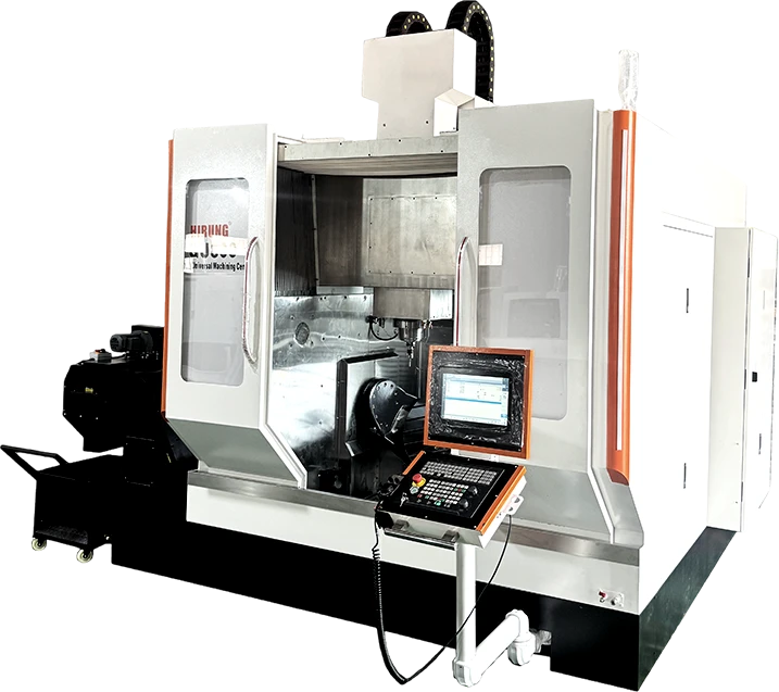
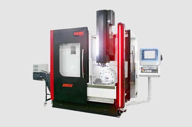
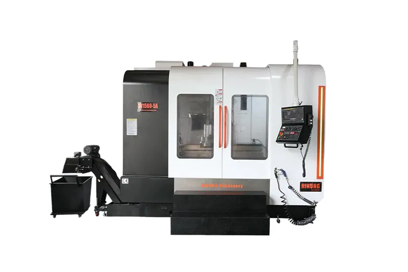
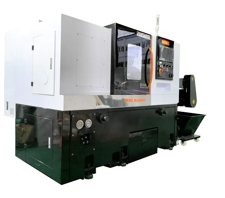
Choosing between a C-frame and a gantry architecture is one of the most critical structural decisions when investing in 5-axis CNC machining. At its core, the choice represents a mechanical trade-off: C-frame designs prioritize compact floor footprints, ergonomic part access, and lower initial capital expenditure for small-to-medium workpieces, whereas gantry configurations prioritize symmetrical dynamic rigidity, uniform thermal dissipation, and heavy workpiece load capacities.
This guide evaluates how structural geometry dictates cutting deflection, long-cycle thermal drift, facility floor requirements, and overall part quality—giving engineering leads and procurement managers an objective framework to select the right platform for their shop floor.

Structural Architecture in 5-Axis Machining: C-Frame vs. Gantry Fundamentals
In 5-axis CNC machining, structural geometry determines how cutting reaction forces flow through the machine bed and how internal and external heat loads translate into tool-center-point (TCP) positional drift. The primary distinction between C-frame and gantry machines lies in the kinematic loop—specifically whether the tool is supported by an open, asymmetrical column or a closed, balanced bridge.
| Structural Feature | C-Frame Architecture (Open Topology) | Gantry Architecture (Closed Topology) |
| Kinematic Structure | Cantilevered open loop | Symmetrical closed frame |
| Top Assembly | Spindle head mounted to a single vertical column | Spindle head suspended from a rigid cross-beam |
| Vertical Support | Single central or rear column | Dual parallel columns or reinforced side walls |
| Base & Table Connection | Bed extends outward under the table from one side | Bed anchors dual uprights around a central table |
| Force Distribution | Single-sided bending load path | Split dual load paths direct to foundation |
A C-frame 5-axis machining center (frequently configured as an open-sided vertical machining center with an integrated trunnion table) mounts the primary spindle ram to a single vertical column projecting upward from the machine bed. The advantage is clear: open access from three sides for manual loading, direct sightlines, and a self-contained base that simplifies transport and placement. However, mechanically, this open profile functions as a cantilever. Cutting forces generated at the tool-workpiece interface exert bending moments on the vertical column.
A gantry-type 5-axis CNC, by contrast, suspends the spindle assembly from a horizontal cross-beam supported symmetrically by two upright columns or elevated walls. Cutting forces are shared across dual structural supports and transmitted straight down into a reinforced base. While a gantry demands more physical space and disciplined shop floor preparation, its closed kinematic loop neutralizes asymmetrical bending and provides superior mechanical resistance against heavy dynamic loads.
When evaluating 5-axis CNC machining solutions, understanding this fundamental mechanical divergence clarifies why each structure behaves differently under varying chip loads, ambient temperatures, and workpiece envelopes.
Rigidity and Dynamic Vibration Damping: How Machine Structure Affects Cutting Loads
Machine tool rigidity consists of both static stiffness (resistance to deflection under continuous load) and dynamic stiffness (resistance to chatter and harmonic vibration during interrupted cuts). In 5-axis milling, rigidity issues compound rapidly because simultaneous rotational axes (A/B/C) shift the cutting vector continuously in three-dimensional space.
| Mechanical Factor | C-Frame Machine Under Cutting Load | Gantry Machine Under Cutting Load |
| Force Transmission Mode | Cantilever load transferred down single column | Force divided equally across two column walls |
| Bending Moment ($M = F \times L$) | High leverage as Z-axis extends down toward table | Minimal moment arm on the cross-beam supports |
| Primary Structural Risk | Microscopic column tilting and resonant chatter | Minor linear deflection without twisting |
| Chatter Threshold | Lower natural frequency under deep roughing cuts | High natural frequency; suppresses harmonic vibration |
| Surface Finish Impact | Requires reduced feeds/DOC on tough alloys to avoid waviness | Maintains consistent micro-inch finishes during high-feed milling |
C-Frame: Cantilever Deflection Under Heavy Milling Loads
On a C-frame machine, the spindle travels along the Z-axis down a vertical column. As the Z-axis extends toward the table to engage a workpiece, the distance from the spindle nose to the column guide-ways increases.
- The Leverage Effect: Any lateral cutting force ($F$) acting on the cutter creates a bending moment proportional to the distance ($L$) from the guide bearings ($M = F \times L$).
- Dynamic Deflection: When performing roughing passes on hard materials like titanium alloys or pre-hardened tool steels, high radial forces can produce microscopic elastic flexing at the column base.
- Surface Chatter: This deflection lowers the machine’s dynamic natural frequency, making it more susceptible to harmonic chatter. This requires operators to reduce depths of cut (DOC) or feeds to maintain acceptable surface finishes and prevent premature tool chipping.
Gantry: Closed-Box Symmetrical Support for Maximum Structural Stiffness
A gantry architecture distributes lateral and vertical cutting loads across its dual-column portal frame.
- Direct Force Flow: Because the cross-rail is supported on both ends, cutting forces split across two separate structural members rather than leveraging a single column.
- Torsional Resistance: Modern gantry frames utilize box-in-box or cast-iron double-wall construction, significantly boosting torsional and bending stiffness.
- Aggressive Material Removal: With resonant frequencies kept high and structural flex minimized, a gantry machine allows aggressive material removal rates (MRR) without inducing vibration. This protects ball screws, rotary encoders, and tool coatings during heavy 5-axis roughing operations.
Thermal Stability: Managing Thermal Drift in Long-Run Precision Machining
Thermal displacement often accounts for a substantial portion of overall volumetric machining errors. Heat generated by high-speed spindles, axis drive motors, ball screws, and hydraulic systems—combined with day-to-night ambient factory temperature swings—causes metal casting structures to expand. How that expansion manifests depends entirely on frame symmetry.
| Thermal Factor | C-Frame Architecture | Gantry Architecture |
| Thermal Geometry | Asymmetrical thermal expansion profile | Symmetrical heat dissipation and expansion |
| Deformation Pattern | Angular column tilt (bowing forward/backward) | Uniform vertical growth along the Z-axis |
| TCP Drift Characteristics | Dual-axis error: simultaneous Y-tilt and Z-drop | Single-axis error: predictable vertical elevation |
| Software Compensation | Demands multi-axis sensor arrays and algorithmic correction | Easily offset with standard automated touch probes |
| Cycle-Length Suitability | Best for short-to-medium runs with regular tool touches | Ideal for 20+ hour continuous multi-surface finishing |
Asymmetrical Thermal Expansion in C-Frame Designs
A standard C-frame is inherently asymmetrical. The front of the column faces the work zone, while the rear houses the counterweights, drive systems, and structural ribbing.
When the machine heats up, the column does not expand purely in a vertical direction. Instead, differential temperatures between the front, back, and sides induce an angular thermal bend—often referred to as “column bowing” or nodding. This tilting motion causes the tool tip to drift unpredictably across the Y and Z axes simultaneously. While real-time software compensation and chiller circuits mitigate this drift, managing complex thermal tilt over an extended 16-to-24-hour cycle requires frequent probing and continuous sensor recalibration.
Symmetrical Heat Dissipation in Gantry Structures
Gantry systems exhibit superior thermal behavior due to structural symmetry.
- Uniform Thermal Growth: Because the structural columns mirror each other across the primary machining zone, thermal expansion occurs evenly along both sides of the bridge.
- Predictable Linear Offsets: Rather than tilting or pitching off-axis, thermal expansion in a gantry translates primarily as a linear shift along the Z-axis.
- Simplified Compensation: Linear vertical shifts are straightforward for CNC controls and tool-center-point management (TCPM) software to detect and offset via automated spindle probes. For aerospace parts and multi-cavity optical molds requiring 30+ hours of continuous finish machining, gantry structures ensure tighter surface continuity across shifts.
Footprint vs. Work Envelope: Real-World Shop Floor Considerations
Adding 5-axis capacity requires aligning machine dimensions with facility constraints, foundation load capacities, and daily workflow mechanics.
| Facility Requirement | C-Frame Configuration | Gantry Configuration |
| Floor Footprint Ratio | High volume-to-envelope efficiency (compact) | Expansive layout; requires perimeter buffer zones |
| Foundation Specifications | Standard 150–200 mm reinforced concrete slab | Dedicated isolated slab or deep-pit foundation |
| Overhead Clearance | Fits within standard industrial ceiling heights | Requires extra clearance for bridge and overhead cranes |
| Loading Ergonomics | Front/side manual loading; rapid part turnarounds | Overhead crane access; unobstructed drop-in zones |
| Cell Integration | Easy to position into robotic pallet pool cells | Requires large-scale rail systems or dedicated gantry arms |
Floor Space Efficiency: Fixed Footprint of C-Frame Centers
For facilities facing tight square-footage limits, compact 5-axis CNC machining solutions built on a C-frame architecture deliver an outstanding ratio of work envelope to total external footprint.
- Self-Contained Base: Most C-frame machines integrate the chip conveyor, coolant tank, and electrical cabinets within a compact, perimeter-accessible envelope.
- Standard Foundation Compatibility: Because overall machine mass is moderate, C-frame units can usually be installed on standard 150 mm to 200 mm reinforced industrial concrete floors without dedicated deep-pit foundations.
- Ergonomic Workstation: Operators can step directly up to the table, facilitating rapid manual part changeovers, visual inspection, and easy workholding adjustments on quick-turn batches.
Installation Requirements: Foundation and Ceiling Height for Gantry Machines
Gantry machines—whether fixed-table moving-bridge or moving-table portal designs—demand substantial floor space and careful civil engineering.
- Footprint Span: The footprint must accommodate not only the table but also the full over-travel paths of the dual columns and way covers, often doubling or tripling the square footage of an equivalent C-frame.
- Vertical Clearance: Elevated gantry bridges and overhead cable carriers require significant overhead crane and ceiling clearance.
- Dedicated Foundations: Heavy dynamic axis movement can transfer resonance into adjacent machinery unless the unit is anchored to an isolated foundation slab. Buyers must budget for site preparation costs, including deep excavation, rebar reinforcement, and curing time before machine leveling can begin.
C-Frame vs. Gantry: Direct Feature Comparison Matrix
The table below outlines the core mechanical, operational, and facility trade-offs between both architectures:
| Evaluation Parameter | C-Frame 5-Axis Machining | Gantry 5-Axis Machining |
| Structural Frame Topology | Open C-shape vertical column (Cantilever) | Closed double-column bridge / Overhead box |
| Dynamic Rigidity & Damping | Moderate to High; optimal for small/medium parts | Exceptional; handles high chip loads & hard alloys |
| Thermal Deformation Mode | Asymmetrical drift; column bowing across Y/Z | Symmetrical thermal growth; predictable Z-axis rise |
| Workpiece Envelope & Weight | Limited by table tilt-trunnion weight limits | Substantial; table supports heavy, large-scale stock |
| Floor Space Utilization | Highly compact; small footprint-to-envelope ratio | Wide footprint; requires broad perimeter clearances |
| Foundation & Facility Needs | Standard reinforced industrial concrete floor | Isolated slab or dedicated deep-pit foundation often required |
| Operator Access & Loading | Direct front and side access; fast manual setups | Overhead crane loading suited for large/bulky billets |
| Initial Capital Expenditure | Cost-effective; lower machine and installation costs | Higher initial CapEx, site preparation, and shipping |
Selection Framework: Which Configuration Fits Your Part Portfolio?
| Primary Production Driver | Recommended Configuration | Key Operational Reason |
| Part Dimensions $\le$ 600 mm | C-Frame Platform | Maximizes shop floor output density and operator changeover speed. |
| Part Dimensions > 800 mm or Weight > 1,000 kg | Gantry Platform | Neutralizes cantilever deflection and supports massive table loads. |
| High-Mix Prototyping / Medical / Precision Job Shop | C-Frame Platform | Low setup time, direct manual access, and minimal facility capital expense. |
| Hard Metal Aerospace Roughing (Titanium / Inconel) | Gantry Platform | High dynamic stiffness suppresses chatter and protects expensive cutting tools. |
| Multi-Hour Precision Mold Finishing (Die & Mold) | Gantry Platform | Thermal symmetry prevents surface mismatching across continuous shifts. |
When to Choose C-Frame 5-Axis Machining
A C-frame configuration is the practical, cost-efficient choice under the following production conditions:
- Part Dimensions: Workpieces fit within a 200 mm to 600 mm cube, and total billet weight remains safely inside standard trunnion-table limits.
- Mix and Volume: High-mix, low-to-medium volume environments (such as precision contract job shops, medical component manufacturing, and small impellers) requiring frequent operator interaction and fast setups.
- Facility Constraints: Tight floor layout requiring high output density per square meter without foundation modifications.
- Material Spectrum: Predominantly aluminum, brass, engineering plastics, and medium-alloy steels where tool loads do not reach heavy roughing thresholds.
When Gantry 5-Axis Machining Is Non-Negotiable
Investing in a gantry framework becomes necessary when parts exceed standard physical envelopes or demand extreme dynamic stability:
- Large-Scale Components: Workpieces exceed 800 mm to 1,000 mm in length or exceed several tons in weight (e.g., aerospace structural spars, large composite trimming tools, automotive stamping dies, and marine engine blocks).
- Difficult-to-Machine Alloys: Deep cavity roughing in titanium, Inconel, or hardened tool steels where cutting forces demand high dynamic damping to suppress chatter.
- Long Continuous Finishing: Mold finishing runs requiring uninterrupted 20+ hour cycles where ambient temperature swings would otherwise cause unacceptable surface mismatches on asymmetrical frames.
- Overhead Crane Loading: Facilities moving heavy stock via overhead gantry cranes that require an open-top envelope unobstructed by a forward-leaning machine column.
To review available configurations, axis travels, and spindle packages, explore HIRUNG 5-axis CNC machining configurations to match your component geometry with the appropriate machine structure.
Frequently Asked Questions (FAQ)
Can a modern C-frame 5-axis CNC match gantry rigidity through software compensation?
Software features such as active vibration suppression, look-ahead trajectory smoothing, and dynamic kinematic calibration can significantly improve surface quality on a C-frame. However, software compensation cannot overcome the physical limits of dynamic deflection. Under heavy roughing loads in tough alloys, software can only command the tool to slow down; it cannot replace the static and dynamic resistance provided by a closed structural gantry.
How do maintenance and alignment complexity compare between C-frame and gantry machines?
C-frame machines are generally simpler and more economical to align, level, and service because they feature fewer structural axes and a self-contained base. Gantry machines—particularly moving-bridge types with dual synchronized linear motors or dual ball screws on the Y-axis—require precise electronic squaring, cross-beam geometric alignment, and regular checks to prevent mechanical binding across long travel rails.
Does overall machine weight directly correlate with 5-axis dynamic stability?
While total mass is an important factor in absorbing kinetic energy, mass distribution and structural geometry are far more decisive. A lighter gantry structure engineered with optimized internal ribbing and a closed-box bridge can outperform a heavier C-frame machine with an unbalanced column overhang. Structural damping properties (such as using high-grade Meehanite cast iron or polymer mineral casting) combined with a closed kinematic loop matter more than raw machine tonnage alone.
Optimize Your 5-Axis Investment with HIRUNG Engineering Support
Determining the ideal structural platform requires evaluating your component dimensions, part materials, dynamic cutting loads, and facility constraints. Selecting an undersized structure can bottleneck tool performance, while over-specifying a gantry where a compact frame would suffice creates unnecessary floor and capital overhead.
If you are evaluating machine configurations for an upcoming production program, contact HIRUNG’s engineering team. Provide your target part drawings, material specifications, and production requirements to receive a detailed technical review, rigidity assessment, and tailored machine recommendation.
Key Takeaways
- Core Mechanical Distinction: C-frame centers rely on an open cantilever column, while gantry centers use a closed, symmetrical bridge frame that splits cutting forces across dual supports.
- Dynamic Rigidity: Gantry designs deliver higher dynamic stiffness, making them better suited for vibration-free heavy roughing and machining tough aerospace alloys.
- Thermal Growth Behavior: C-frame machines experience asymmetrical angular column tilt during thermal cycles, whereas gantry platforms exhibit symmetrical vertical expansion that is simpler to offset via standard control probes.
- Space and Foundation: C-frame machines optimize floor space and install on standard industrial concrete; gantry machines demand larger shop footprints, overhead clearances, and often dedicated concrete foundations.
- Selection Guideline: Choose C-frame for parts under 600 mm, agile manual changeovers, and medium cutting loads; select gantry for large-scale parts, heavy billets, deep-cavity dies, and high-hour mold finishing.
FAQ
Q: Can a modern C-frame 5-axis CNC match gantry rigidity through software compensation?
A: No. While advanced CNC software can smooth acceleration curves and adjust feed rates to suppress chatter, it cannot overcome the mechanical leverage of an open cantilever column under heavy cutting loads.
Q: How do maintenance and alignment complexity compare between C-frame and gantry machines?
A: C-frame machines are simpler and faster to level and align. Gantry configurations require disciplined geometric leveling, foundation monitoring, and electronic synchronization across dual drive axes to prevent bridge skewing.
Q: Does machine weight directly correlate with 5-axis dynamic stability?
A: Mass helps damp vibration, but geometric topology is more critical. A well-ribbed closed gantry frame dampens dynamic cutting forces more effectively than a heavier C-frame burdened by an extended cantilever arm.