Choosing between continuous 5-axis and 3+2 axis machining comes down to geometric necessity versus structural rigidity. If a workpiece requires continuous tool vector adjustments across organic, non-developable surfaces—such as an impeller blade or an aerospace blisk—true simultaneous multi-axis motion is non-negotiable. If the objective is simply accessing five sides of a prismatic part in a single setup, 3+2 positional machining offers superior structural stiffness, simpler programming, and lower tooling overhead.
Machine shops frequently overpay for simultaneous multi-axis licenses and hardware when positional indexing accounts for upwards of 85% of complex production work. Conversely, purchasing an indexed setup for continuous surface designs leads to scrapped parts, tool gouging, and manual rework.
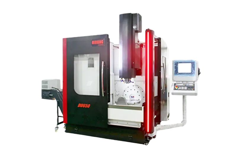
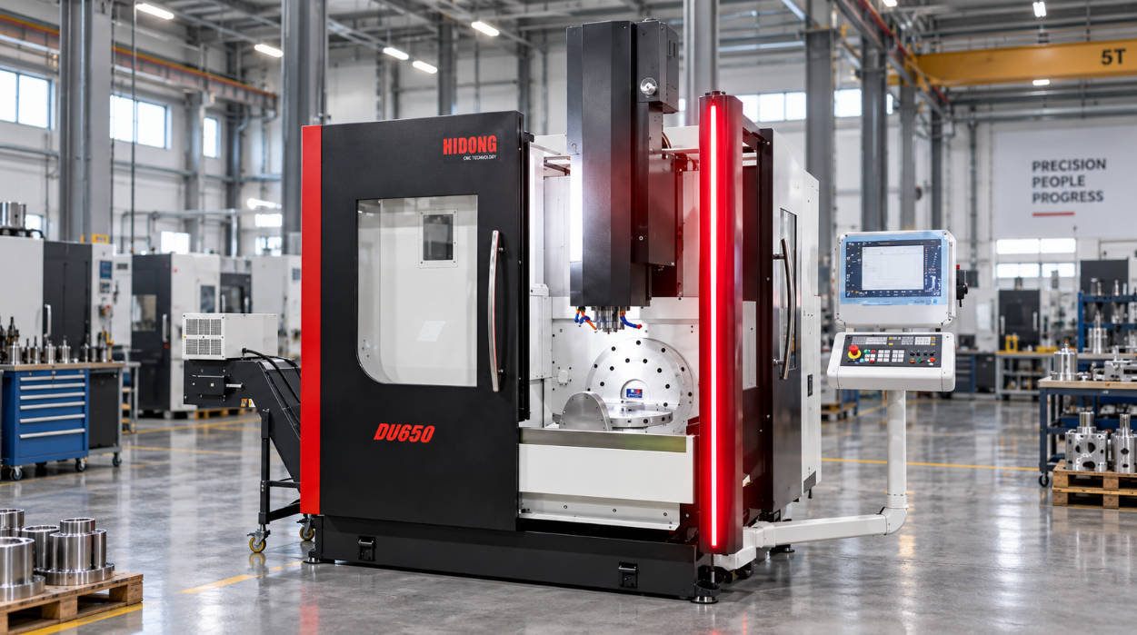
Understanding the kinematic differences, programming demands, rigid dynamic limitations, and total investment profiles of modern 5-axis CNC machining centers allows machine shop owners and manufacturing engineers to deploy capital where cycle time and volumetric accuracy justify the expense.
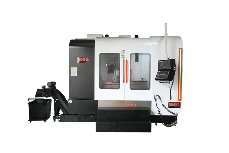
Kinematics & Workflow: Continuous 5-Axis vs. 3+2 Positional Machining Defined
The fundamental distinction between continuous 5-axis and 3+2 axis machining centers lies in how the rotary axes behave relative to the cutting tool path.
Continuous 5-Axis Machining (Simultaneous 5-Axis)
Continuous 5-axis machining moves three linear axes (X, Y, Z) and two rotary axes (either A/B, A/C, or B/C) synchronously while the cutting tool removes material. The CNC controller recalculates the tool axis orientation in real time, maintaining an optimal cutting angle, chip load, and lead/tilt contact point throughout the entire cut.
Modern simultaneous machining relies on Tool Center Point Control (TCPC) or Rotary Tool Center Point (RTCP). This controller feature automatically compensates for the pivot-length offset of the rotary axes. Programmers generate toolpaths based on part coordinates rather than machine pivot centerlines, preventing gouging across complex 3D sweeps.
3+2 Axis Machining (Positional / Indexical Machining)
In 3+2 axis machining, the machine uses two rotary axes to tilt and orient the workpiece or spindle into a fixed spatial position, locks the mechanical rotary brakes, and then executes a traditional 3-axis toolpath along X, Y, and Z. The rotary axes remain stationary during cutting.
This technique is frequently called positional 5-axis machining. It functions through spatial plane transformations in the controller (such as Siemens CYCLE800, Fanuc G68.2, or Heidenhain PLANE Spatial). These cycles establish a local, tilted coordinate system, allowing operators to mill pockets, drill angled cross-holes, and face compound angles without manual reclamping or continuous rotary motion.
Side-by-Side Evaluation: Rigidity, Programming, and Operational Dynamics
Both multi-axis architectures significantly reduce manual handling errors compared to 3-axis mills, but their structural and computational behaviors differ considerably on the shop floor.
| Evaluation Metric | 3+2 Axis Positional Machining | Continuous (Simultaneous) 5-Axis |
| Axis Motion State | Rotary axes locked during the cut; linear axes cut. | All 5 axes interpolate simultaneously during cutting passes. |
| Mechanical Rigidity | High; mechanical rotary brakes lock trunnion/head solid. | Dynamic; system stiffness depends on direct-drive motor torque and continuous bearing load limits. |
| Tool Length & Deflection | Short tools positioned directly over tilted features minimize chatter. | Short tools with dynamic clearance tilt, though cutting forces vary across changing contact vectors. |
| CAM Programming Complexity | Moderate; standard 3-axis toolpaths projected onto tilted coordinate planes. | High; requires collision avoidance, vector lead/lag angle controls, and tilt limits. |
| Post-Processor Requirements | Standard; tilted work plane macros are robust across major CAM systems. | Critical; requires custom kinematics, continuous TCPC support, and full kinematic simulation. |
| Operator Skill Floor | Readily accessible to experienced 3-axis CNC programmers. | Requires dedicated training in multi-axis simulation, vector clearance, and dynamic feed control. |
| Initial Investment & Overhead | Lower entry cost; uses standard CAM post-processors and 3-axis CAM seats. | Higher capital expenditure; requires multi-axis CAM upgrades and verification software. |
Cutting Rigidity and Vibration Dampening
In 3+2 operations, locking the rotary axes with mechanical or pneumatic brakes transforms the machine into a rigid 3-axis milling platform. This setup dampens harmonic chatter during heavy roughing passes, allowing shops to push aggressive chip-thinning feed rates and larger indexable face mills into high-temp alloys or tool steels.
Simultaneous 5-axis machining cannot clamp its rotary axes during profiling cuts. The drive system—whether worm gear, roller cam, or direct-drive torque motor—must maintain positional accuracy against changing cutting pressures. Pushing excessive radial depth of cut during continuous contouring can deflect rotary drives, leaving visible faceted marks or chatter bands on critical surfaces.
CAM Programming and Collision Verification
Programming a 3+2 setup requires setting a work coordinate system (WCS) on a tilted plane and generating standard 2.5D or 3D toolpaths. Collision detection remains relatively straightforward because the tool orientation stays static throughout each operation.
Continuous 5-axis programming demands dynamic tool vector management. The programmer must control how the tool leans into the cut, prevent the tool shank from colliding with deep wall cavities, and keep the spindle head away from trunnion fixtures. Continuous toolpaths generally require full kinematic machine simulation (e.g., VERICUT or integrated CAM machine simulation) to verify machine over-travel limits and prevent collisions.
Application Matchmaker: Which Workpieces Require True 5-Axis vs. 3+2 Axis?
Matching part geometry to machine architecture prevents shops from buying excess capability or taking on work their equipment cannot produce accurately.
Is the workpiece surface non-developable, requiring continuous vector changes?
  ├── YES  ──> Continuous 5-Axis Required (Impellers, blisks, turbine blades, complex prosthetics)
  └── NO   ──> Are features distributed across multiple angled planes?
                ├── YES  ──> 3+2 Axis Positional is Optimal (Manifolds, gearbox housings, core/cavity plates)
                └── NO   ──> Standard 3-Axis / Single-Setup VMC
Workpieces Requiring Continuous 5-Axis Machining
Simultaneous 5-axis is mandatory when the cutter contact point must sweep smoothly across continuously changing 3D geometry:
- Impellers, Blisks, and Inducers: Twisted, twisted-hub flow channels and overlapping blades prevent direct line-of-sight access from any single tilted angle.
- Turbine Blades and Airfoils: Variable aerodynamic profiles require the tool flank or radius to sweep along shifting compound vectors to maintain surface finish without scallop steps.
- Complex Orthopedic Implants: Femoral knee components and hip stems feature organic, freeform surfaces that require continuous ball-nose multi-axis blending.
- Deep, Undercut Mold Cavities: Deep cavities with negative draft angles demand continuous tool tilt to reach under side walls with short, rigid end mills.
Workpieces Suited for 3+2 Positional Machining
Positional 3+2 machining handles parts that are geometrically planar or feature-based, distributed across multiple faces:
- Hydraulic and Pneumatic Manifolds: Complex blocks containing cross-drilled passages, threaded ports, counterbores, and angled face mills across five sides.
- Aerospace Structural Brackets and Ribs: Pocketing, mounting ears, and fastener holes angled across stiffening ribs.
- Die and Mold Bases: Deep pockets, cooling channels, side-slider retention slots, and ejector pin holes machined into hardened tool steels requiring high cutting rigidity.
- Gearbox and Transmission Housings: Multi-sided casting components that need bore finishing, face milling, and tapped holes in tight alignment without stacking refixturing tolerances.
Evaluating these geometry types alongside dedicated 5-axis machining solutions ensures the machine configuration matches shop floor production demands.
Total Cost of Ownership (TCO): Machine Price, Software, and Shop Floor ROI
Evaluating multi-axis equipment requires looking beyond base machine purchase price. Capital investments encompass software seats, fixturing systems, operator training, and collision risk mitigation.
Capital Outlay and Tooling Expenses
A dedicated simultaneous 5-axis machining center equipped with high-resolution optical encoders, direct-drive rotary motors, and advanced CNC look-ahead controllers carries a premium over a 3+2 configured center. In 3+2 platforms, standard geared rotary tables or simpler indexing configurations can be paired with high-performance vertical machining centers at lower capital cost.
Tooling expenses also vary between configurations:
- Fixturing: Both approaches leverage modular zero-point clamping systems and dovetail vises to elevate the part, granting five-sided spindle clearance.
- Cutting Tools: 3+2 machining relies on shorter, rigid standard cutters that cost less and maintain predictable deflection profiles under high feeds.
- Software Licensing: Standard CAM licenses frequently support 3+2 indexed planes out of the box. Adding full simultaneous 5-axis toolpath modules (swarf milling, multi-axis contouring, automated tilt collision avoidance) introduces recurring seat subscription costs and machine-specific post-processor development fees.
Cycle Time Reductions vs. Overhead Payback
The return on investment (ROI) for 3+2 machining stems from consolidating multiple manual setups into a single machine cycle (the “done-in-one” concept):
- Eliminates two to four soft-jaw refixturing cycles per part.
- Removes accumulated datum transfer errors between separate setups, cutting scrap rates on precision tolerance parts.
- Reduces work-in-progress (WIP) storage and manual operator handling between machines.
Continuous 5-axis ROI comes from producing parts that are otherwise impossible to machine or require hours of manual bench polishing. Using point-milling with a tilted tool or flank-milling with the side of an end mill can replace fine-stepover 3D ball-nose rastering, shortening cycle times on freeform components by 40% to 70%.
The 4-Step Decision Framework: Selecting the Right Architecture for Your Shop
Use this four-step engineering framework to identify which multi-axis layout matches your operational targets.
Step 1: Analyze Part Geometries (Continuous Contours vs. Planar Facets)
Review your current quote volume and blueprint history for the past 12 to 24 months:
- Do your prints specify organic aerodynamic surfaces, non-uniform rational B-spline (NURBS) surfaces, or deep negative drafts that cannot be cut from a single static tool axis? Choose Continuous 5-Axis.
- Do your prints feature angled bores, multi-sided port faces, angled dowel holes, or orthogonal pockets spread across multiple sides? Choose 3+2 Axis.
Step 2: Audit CAM Capabilities and Technical Labor
Multi-axis hardware depends on the programmer’s ability to drive it safely:
- Does your team have experience with multi-axis vector programming, kinematic simulation, and custom post-processors? If not, adopting continuous 5-axis introduces a 3- to 6-month learning curve accompanied by collision risk.
- Can your existing workforce program standard 3-axis paths? If yes, adopting 3+2 machining requires only minimal training on tilted work plane coordinate macros.
Step 3: Assess Batch Size and Mix (HMLV vs. High-Volume Production)
- High-Mix, Low-Volume (HMLV): 3+2 machining excels in job-shop environments because parts can be set up in a standard self-centering vise and programmed quickly using familiar toolpaths.
- Dedicated Production Runs: If producing dedicated components with tight cycle-time targets (such as medical orthopedics or impeller impellers), true continuous 5-axis cycles optimize chip-load consistency and tool engagement.
Step 4: Plan for Future Shop Expansion
Consider the market sectors your shop intends to pursue over the next three to five years. If your business plan targets certified aerospace turbine contracts, medical implant manufacturing, or advanced optical mold components, investing upfront in customized 5-axis CNC machining configurations provides the kinematic capabilities required to win and deliver those orders.
Frequently Asked Questions (FAQ)
Can a simultaneous 5-axis machine also perform 3+2 positional machining?
Yes. Every continuous 5-axis machine can run 3+2 positional toolpaths by locking its rotary axes (mechanically or via closed-loop servo control) and applying standard tilted plane commands (such as G68.2 or CYCLE800). Many shops with simultaneous multi-axis machines use them primarily in 3+2 mode for prismatic parts, reserving continuous five-axis interpolation for dedicated contouring features.
Do I need an advanced 5-axis CAM license if I only run 3+2 operations?
In most CAM systems, no. Positional 3+2 toolpaths are fundamentally 3-axis toolpaths oriented onto a local work plane. Many software providers include 3+2 indexing in their intermediate 3-axis milling packages, which avoids the cost of full 5-axis multi-surface modules.
Is 3+2 machining more rigid than continuous 5-axis machining?
Yes, in most machine structural configurations. When running 3+2 operations, the machine engages mechanical or pneumatic rotary axis clamps, isolating the worm drives or direct-drive torque motors from dynamic cutting forces. This configuration provides a stiffer machining platform for heavy milling, deep slotting, and aggressive roughing cuts.
When does a continuous 5-axis toolpath provide better tool life than 3+2 machining?
Continuous 5-axis toolpaths extend tool life on organic 3D shapes by tilting the cutter to avoid running a ball-nose end mill at its center point, where cutting velocity drops to zero. Tilting the tool maintaining a constant contact radius and cutting speed along complex contours, preventing chipping and uneven tip wear.
Key Takeaways
- Kinematic Difference: Continuous 5-axis coordinates all 5 axes simultaneously during the cut; 3+2 positional machining locks the rotary axes at tilted angles and executes standard 3-axis toolpaths.
- Rigidity vs. Flexibility: 3+2 machining provides greater mechanical stiffness and vibration dampening through mechanical axis brakes, making it ideal for aggressive roughing and high-temp alloy milling.
- Geometric Requirements: True 5-axis is required for non-developable, organic shapes (impellers, blisks, complex prosthetics). 3+2 excels at prismatic, multi-sided parts (manifolds, pump housings, mold bases).
- Software and Skill Demands: 3+2 machining integrates easily with standard 3-axis programming workflows; continuous 5-axis requires dedicated multi-axis CAM licenses, comprehensive collision simulation, and experienced programmers.
- Capital Allocation: Choosing a machine based on blueprint geometric requirements avoids paying for unused simultaneous toolpath capabilities while ensuring your shop can maintain target volumetric accuracy.