Evaluating 5 axis machining centers requires looking past top-line catalog ratings to understand how dynamic stiffness, control algorithms, and thermal stability behave under actual cutting loads. Investing in a multi-axis CNC platform is a significant capital commitment; choosing mismatched specifications often leads to tool chatter, geometric inaccuracy, surface finish degradation, and extended cycle times.
To determine the right machine configuration for your production floor, prioritize these seven technical criteria: spindle power and torque curves, linear and rotary positioning tolerances, kinematic architecture and table load capacities, CNC controller block processing with real-time kinematic compensation, thermal stabilization mechanisms, effective volumetric work envelopes, and peripheral automation interfaces.
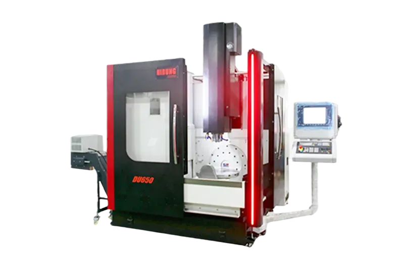
Beyond the Spec Sheet: Why Evaluating 5-Axis Specifications Dictates ROI
A standard sales brochure rarely tells the full engineering story. Two machines sharing identical nominal dimensions and peak spindle speeds can exhibit vastly different throughput, tool life, and volumetric accuracy on identical workpieces.
Misjudging machine specifications typically introduces distinct production bottlenecks:
- Insufficient torque at target RPM: Results in shallow cut depths and excessive cycle times in hard metals.
- Under-dimensioned rotary axes: Creates deflection, resonant vibration, and poor surface finishes during simultaneous continuous cutting.
- Inadequate controller interpolation: Forces the machine to decelerate through complex 3D toolpaths, causing micro-faceting.
- Uncontrolled thermal expansion: Causes dimensional drift across multi-hour production runs.
Evaluating your options through an engineering-driven procurement lens protects part quality and operational margins. When planning capital acquisitions across precision manufacturing sectors, selecting 5-axis CNC machining centers configured around realistic cutting forces—rather than static showroom numbers—is the foundation of long-term profitability.
Spec 1: Spindle Power, Torque Curves, and Taper Interface
The spindle serves as the core cutting interface. Selecting a spindle based entirely on maximum speed (RPM) often leads to performance mismatches if the torque output curve does not align with your primary workpiece alloys.
High-Speed Machining (HSM) vs. High-Torque Heavy Cutting
Spindle performance relies on the interplay between continuous power (S1), intermittent peak power (S6), base speed, and torque delivery:
- High-Speed Machining (15,000 to 24,000+ RPM): Geared toward aluminum alloys, micro-machining, medical components, and fine finishing for mold tooling. These motorized (built-in) spindles prioritize low rotational inertia and rapid acceleration, but their torque drops off sharply at lower rotational speeds.
- High-Torque Profiling (6,000 to 12,000 RPM): Essential for heat-resistant superalloys (such as Inconel and titanium) and structural steel dies. These applications require robust low-end torque—often exceeding 150 to 300 Nm—to push heavy indexable cutters through high-shear cuts without stalling or chattering.
Tooling Interface: HSK vs. BT and Dual-Contact Standards
Rotary tool deflection multiplies when tilting cutters through five degrees of freedom:
- HSK Toolholders (HSK-A63, HSK-A100): Feature a 1:10 hollow taper that expands outward under centrifugal force, locking both the taper and the flange flat against the spindle face. This dual-contact interface provides superior radial stiffness, precise axial repeatability, and balanced dynamics at high speeds.
- BT and BBT (Big-Plus) Toolholders: Standard BT taper formats rely on steep 7:24 taper geometry. For heavy-duty low-frequency milling, dual-contact systems (BBT) offer an alternative by securing both face and taper contact, preventing the toolholder from pulling back into the spindle socket under extreme axial loads.
| Target Material / Application | Recommended Speed Range (RPM) | Primary Spindle Requirement | Preferred Tooling Interface |
| Aluminum & Thin-Wall Aerospace | 18,000 – 24,000+ | Fast acceleration, dynamic balancing | HSK-A63 |
| Hardened Tool Steels (Die & Mold) | 12,000 – 18,000 | Balanced torque and vibration damping | HSK-A63 / BBT40 |
| Titanium & Nickel Superalloys | 6,000 – 10,000 | High continuous torque (>150 Nm) | HSK-A100 / BBT50 |
| Micro-Parts & Precision Medical | 20,000 – 40,000+ | Ultra-low runout, low thermal growth | HSK-E40 / HSK-A63 |
Spec 2: Positioning Accuracy and Repeatability (VDI/DGQ 3441 vs. ISO 230-2)
Machine tolerance statements vary depending on the international testing protocol applied. Evaluating machine capabilities requires standardizing measurement parameters and confirming feedback mechanisms.
Standardized Tolerance Protocols
Manufacturers typically document positional accuracy ($A$) and repeatability ($R$) using either ISO 230-2 or VDI/DGQ 3441 standards.
- ISO 230-2 applies a bidirectional statistical assessment over multiple target positions, filtering out localized measurement anomalies.
- VDI 3441 tends to reflect broader statistical spreads.
When comparing competitive equipment proposals, verify which testing standard is cited. A machine rated at $\pm0.005\text{ mm}$ under a localized, unidirectional test may show wider variance under full bidirectional dynamic checks across the entire axis stroke.
Optical Linear Scales and Direct-Drive Rotary Encoders
Semi-closed loop control systems rely on rotary motor encoders at the end of the ball screw. In 5-axis setups, this approach leaves thermal screw growth, mechanical backlash, and pitch errors unmeasured.
- Linear Optical Scales: Sealed glass scales on the linear axes (X, Y, and Z) provide direct, full closed-loop positional feedback to the CNC controller, bypassing mechanical transmission inaccuracies.
- Rotary Encoders: High-resolution optical or magnetic ring encoders mounted directly to the center of rotation on the rotary axes (A, B, or C) are critical. Because angular errors multiply over extended tool projection lengths, direct rotary feedback ensures tight positioning tolerances across challenging spatial vectors.
Spec 3: Kinematic Architecture and Rotary Table Load Capacity
The mechanical arrangement of a 5-axis platform dictates cutting rigidity, maximum workpiece dimensions, and overall dynamic responsiveness. Machine layouts fall into two primary kinematic architectures:
Trunnion Table (Table-Table) vs. Swivel Head (Head-Table / Head-Head)
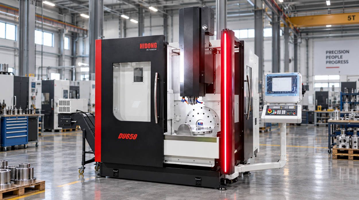
- Trunnion Style (Tilting Rotary Table): The cutting tool moves strictly along linear axes (X, Y, Z), while the workpiece tilts (A or B axis) and rotates (C axis). This configuration provides high structural rigidity, making it effective for medium-to-small parts, intricate medical hardware, impellers, and compact mold cavities. However, tilting heavy fixtures shifts the workpiece’s center of gravity away from the pivot line, altering dynamic stability.
- Swivel Head Style (Articulating Spindle Head): The spindle head tilts along the B or A axis, while the table either remains stationary, rotates along the C axis, or moves along a traveling column. This layout handles heavy, bulky castings, automotive bumper molds, and long aerospace structural frames because table load limits do not restrict rotary axis acceleration.
Rotary Drive Mechanisms: Gear Drives vs. Direct Drive Motors
- Worm Gear and Roller Gear Cams: Offer high mechanical torque multipliers and natural holding stiffness for heavy roughing cuts. However, gear mechanisms experience physical wear over time, which can introduce mechanical backlash if not regularly maintained and compensated.
- Direct Drive (DD) Torque Motors: Eliminate mechanical gearing entirely by integrating torque motors directly into the rotary axes. Direct drive designs deliver high rotational velocities, zero mechanical backlash, and fast reversal response, making them suitable for continuous simultaneous contouring. However, heavy intermittent milling requires integrated high-pressure hydraulic or pneumatic clamping systems to arrest the rotary axes during heavy 3+2 operations.
Spec 4: CNC Controller Processing Speed and Real-Time Kinematic Compensation
A 5-axis machine frame cannot deliver tight tolerances without a controller capable of processing dynamic multi-axis trajectory mathematics in real time.
| Processing Stage | System Function | Primary Operational Purpose |
| 1. CAD/CAM Input Stream | High-density 3D toolpath decomposition | Feeds small linear segments describing freeform contoured surfaces. |
| 2. Look-Ahead Buffer | Multi-block trajectory pre-parsing (1,000+ blocks) | Analyzes curvature changes in advance to calculate optimal acceleration profiles without sudden axis stops. |
| 3. Kinematic Vector Calculation | RTCP / TCPC real-time coordinate transformations | Continually recalculates pivot offsets to lock the tool tip on the programmed surface vector regardless of table/head tilt. |
| 4. Servo Execution & Filtering | Dynamic acceleration, jerk filtering, and drive execution | Smooths motion output across all 5 axes simultaneously to eliminate micro-faceting and machine resonance. |
RTCP (Rotational Tool Center Point) and Look-Ahead Capabilities
Simultaneous 5-axis operations require dedicated algorithms—such as RTCP or TCPC—to maintain the tool tip precisely on the programmed surface vector:
- Tool Center Point Management: Without RTCP, programming paths requires tying coordinates directly to the exact pivot length of the physical machine. With RTCP enabled, the controller automatically recalculates linear axis offsets in real time as the rotary axes tilt and spin, compensating for tool wear and tool length variations automatically.
- Block Processing Time (BPT) & Look-Ahead: High-speed surface machining translates complex 3D contours into thousands of micro-line segments per second. A controller with low processing latency and an expanded look-ahead buffer (evaluating 1,000 blocks or more in advance) predicts axis jerk, applying smooth acceleration/deceleration profiles without stuttering or leaving facet marks on contoured surfaces.
- Dynamic Collision Monitoring (DCM): Integrated real-time geometric collision detection halts the machine within milliseconds if an axis vector brings the spindle nose, tool assembly, or workpiece into interference with the table structure or enclosure.
Spec 5: Thermal Stability Systems and Static Machine Mass
Thermal variance is a primary driver of unexplained dimensional shift in precision CNC milling. Frictional heat from ball screws, spindle bearings, motors, and fluctuating ambient shop air causes structural machine frames to expand unevenly.
Frame Casting Materials and Symmetry
- Meehanite Cast Iron: High-grade, stress-relieved cast iron dampens vibrations effectively and resists structural deformation during cyclical cutting impacts.
- Polymer Composite / Mineral Casting: Mineral composite castings provide vibration damping characteristics multiple times higher than structural steel weldments, accompanied by low thermal conductivity that buffers short-term ambient shop temperature swings.
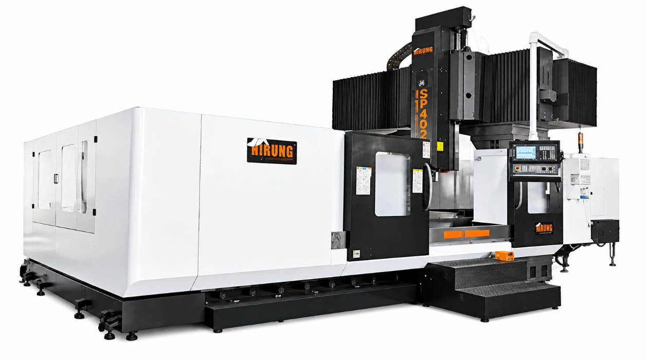
- Symmetrical Structural Design: Box-in-box and portal-style machine designs distribute cutting forces and thermal gradients symmetrically along the machine center, avoiding thermal deflection patterns common to asymmetrical C-frame layouts.
Active Cooling Circuits
A reliable thermal package should include:
- Chilled Spindle Jackets: Refrigerated coolant circulates continuously around the spindle sleeve and motor windings to extract motor heat.
- Core-Cooled Ball Screws: Chilled oil or fluid pumped through the center of linear ball screws dissipates heat generated by rapid, repetitive axis reversals.
- Thermal Sensors and Real-Time Algorithmic Compensation: Strategically placed temperature probes across the casting frame, spindle housing, and axis nuts feed real-time expansion coefficients back into the CNC numerical model to offset coordinate datums automatically.
Spec 6: Working Envelope and Angular Travel Limits
Evaluating an axis travel table on paper requires distinguishing between total axis stroke and the effective volumetric working envelope when actual parts, fixtures, and extended cutters are installed.
| Envelope Dimension Factor | Engineering Restriction | Net Effect on Usable Work Zone |
| Total Linear Stroke | Nominal manufacturer axis limits (X, Y, Z) | Maximum mechanical displacement without tooling or workholding. |
| Workholding Stack Height | Zero-point receiver plates, chucks, and self-centering vises | Consumes vertical Z-axis clearance and reduces usable part height. |
| Tool Assembly Projection | Gauge length of toolholder plus extended cutter stick-out | Increases minimum spindle distance required to clear top surfaces. |
| Rotary Tilt Clearance (A/B Axes) | Table edge or head clearance at steep angular orientations | Sweeps workholding upward and outward, restricting effective X/Y boundaries. |
Angular Limits and Tool Clearance
- Rotary Axis Tilt Range: A tilting table rated at $\pm110^\circ$ or $\pm120^\circ$ of travel allows for undercut machining and back-boring operations. However, as the table tilts toward its maximum angle, the edge of the pallet sweeps upward into the Z-axis workspace.
- Spindle Nose-to-Table Distance: Measure the minimum and maximum distance between the spindle nose and the table face. Insufficient travel along the Z-axis may prevent long drills from clearing the part when the table tilts fully upward. Conversely, excess clearance can force you to run extended toolholders for shallow cuts, increasing chatter and reducing tool life.
- Zero-Point Fixturing Overhead: Factoring in the stack height of modular baseplates, pneumatic chucks, and five-axis self-centering vises reduces usable vertical headroom. Always evaluate three-dimensional collision envelopes inside your CAM software rather than relying solely on linear travel dimensions.
Spec 7: Productivity Infrastructure: ATC Capacity, Chip Flushing, and Pallet Automation
Machining complex parts in a single setup demands sufficient auxiliary tool and chip management support. When secondary operations are integrated into one machine, tool consumption increases.
Tool Magazine Sizing (ATC)
A standard 24-tool carousel is often consumed quickly on a multi-axis platform once standard face mills, drills, taps, chamfer cutters, probes, and specialized ball mills are loaded.
- Look for an automatic tool changer (ATC) offering 40 to 60 pockets or more for flexible production.
- Confirm maximum allowable tool weight, total balanced magazine weight, and maximum tool diameter with adjacent pockets occupied to avoid mechanical tool changer jams.
Chip Management and Coolant Systems
- High-Pressure Through-Spindle Coolant (CTS): Delivering coolant through the tool at pressures between 20 and 70 bar (300 to 1,000 PSI) clears chips from deep cavities, keeps drilling channels cool, and extends cutter life in difficult alloys.
- Internal Washdown and Scraper Conveyors: 5-axis machines feature complex internal enclosures, tables, and way covers. High-volume internal washdown systems, combined with dual-auger spiral conveyors and external hinged-belt or scraper-type chip conveyors, prevent heavy metal chips from packing around rotary table seals and way covers.
- Pallet Automation Preparation: If lights-out production is an operational target, confirm the machine is prepared with pneumatic and hydraulic pass-through lines, automatic door interfaces, and software scheduling for zero-point pallet changers or external robotic tending cells.
Matching 5-Axis Specifications to Industry-Specific Workpieces
Because machine requirements vary by material and part geometry, technical specifications should be matched directly to your primary manufacturing focus:
| Industry / Application | Critical Priority Specs | Spindle Requirement | Axis Feedback & Accuracies | Recommended Architecture |
| Aerospace Turbomachinery (Blisk, Impellers) | Dynamic multi-axis interpolation, high angular rotation speeds | 15,000 – 20,000 RPM, moderate torque, HSK-A63 | Direct optical scales, direct rotary encoders | Trunnion (Table-Table) with Direct-Drive motors |
| Precision Die & Mold (Automotive/Electronics) | Surface finish quality, micro-segment processing, thermal stability | 18,000 – 24,000 RPM, low runout, dynamic balancing | Glass scales, thermal growth compensation modules | Rigid portal/bridge type, Trunnion or Swivel Head |
| Heavy Aerospace Structural (Titanium, Inconel) | Cutting rigidity, structural damping mass, low-end torque | 6,000 – 10,000 RPM, high continuous torque (>200 Nm), HSK-A100 | Full closed-loop glass scales, heavy axis clamping | Traveling Column or Swivel Head (Head-Table / Head-Head) |
| Medical Implants & Instruments (Orthopedics, Bone Plates) | High positioning repeatability, compact footprint, rapid tool change | 20,000 – 30,000+ RPM, low thermal growth | Direct feedback on all axes, dynamic RTCP | Compact High-Speed Trunnion table |
Reviewing your production roadmap against these operational parameters ensures you configure a platform tailored to your shop’s specific component requirements. For operations looking to balance continuous contouring precision with long-term mechanical reliability, reviewing configured 5-axis CNC machining centers provides a practical foundation for shop-floor modernization.
Final 5-Axis Purchasing Evaluation Checklist: Questions to Ask Suppliers
Before finalizing procurement contracts, present machine tool builders and distributors with these technical qualification questions:
| Evaluation Area | Inspection Item & Verification Question | Target Engineering Confirmation |
| 1. Accuracy Standards | Under what specific protocol (ISO 230-2 or VDI/DGQ 3441) are positioning tolerances validated? | Obtain verified bidirectional factory laser interferometer reports. |
| 2. Scale Feedback | Are linear optical scales and rotary ring encoders included standard? | Confirm full closed-loop feedback on linear axes (X/Y/Z) and rotary axes. |
| 3. Spindle Output | Can the builder provide continuous (S1) and intermittent (S6) torque curves? | Validate torque output at target base RPM against workpiece alloys. |
| 4. Thermal Management | What active fluid circuits and real-time sensors are integrated into the frame? | Verify spindle jacket cooling, core-cooled ball screws, and algorithmic drift offsets. |
| 5. Rotary Axis Drives | Are rotary axes driven by direct-drive torque motors or mechanical gear systems? | Confirm continuous dynamic contouring speeds and hydraulic clamping torque. |
| 6. Motion Algorithms | Are RTCP/TCPC, 1,000+ block look-ahead, and dynamic collision monitoring standard? | Ensure advanced multi-axis software features are fully unlocked in the controller package. |
| 7. Working Envelope | Has CAM clearance been simulated with target workpieces, fixtures, and cutters? | Check interference zones at maximum angular tilt angles ($\pm110^\circ / \pm120^\circ$). |
| 8. Empirical Testing | Can the builder execute a standard cutting test before factory acceptance? | Request an ISO 10791 or NAS 979 circle-diamond-square test cut report. |
Key Takeaways
- Evaluate Torque Curves, Not Just Top RPM: Ensure continuous spindle power matches workpiece shear requirements. High RPM is ideal for light alloys and mold finishing, but tough materials demand low-end torque and rigid toolholder interfaces (such as HSK-A63, HSK-A100, or dual-contact tapers).
- Demand Direct Closed-Loop Scale Feedback: Angular errors multiply over extended cutter lengths. Relying solely on motor-encoder positioning leaves thermal growth and mechanical backlash unmeasured; insist on linear glass scales and direct-drive rotary encoders.
- Match Kinematic Layout to Workpiece Mass: Trunnion table (table-table) designs provide high rigidity for compact-to-medium parts, whereas swivel-head systems isolate heavy part mass from the tilting axes for large, heavy workpieces.
- Controller Software is as Critical as the Machine Casting: High dynamic accuracy depends on advanced RTCP interpolation algorithms, micro-segment look-ahead buffers, and real-time dynamic collision prevention.
- Factor in the Entire Fixture and Tooling Stack: Total axis stroke does not equal usable space. Always calculate the volumetric envelope with modular zero-point clamping plates, tall vises, and extended tool assemblies at maximum tilt.
Frequently Asked Questions (FAQ)
What is the difference between simultaneous 5-axis and 3+2 positional machining?
Simultaneous 5-axis machining moves all five axes (three linear and two rotary) concurrently along programmed continuous trajectories, which is required for sculpting impellers, complex airfoils, and continuous 3D molds. In 3+2 axis machining (positional 5-axis), the two rotary axes position and lock the workpiece at an angular vector, after which the three linear axes perform standard milling. While 3+2 machining simplifies programming and provides high rigidity for prism parts, true simultaneous capabilities are essential for freeform contoured geometries.
Why is RTCP (Rotational Tool Center Point) necessary for 5-axis milling?
RTCP allows the CNC controller to track the center point of the cutting tool in real time relative to the part coordinate system, regardless of the rotational axis tilt angle or pivot center distance. Without RTCP, any change in tool length, regrinding, or wear requires completely reposting the CAD/CAM program. With RTCP active, the controller handles kinematic coordinate offsets dynamically on the fly.
Should I choose a direct-drive rotary table or a worm-gear drive?
Direct-drive (DD) tables utilize brushless torque motors without mechanical reduction gears, providing high rotational speeds, zero mechanical backlash, and rapid response for simultaneous contouring. Worm gears or roller gear cams offer mechanical torque multiplication and high resistance to heavy cutting forces during roughing cuts, but mechanical gears wear over time and introduce backlash that requires periodic mechanical adjustment.
How does thermal compensation work on a multi-axis CNC machine?
Thermal compensation systems combine thermal symmetry design, physical cooling circuits, and algorithmic compensation. Refrigerated chillers circulate cooled fluid through the spindle sleeve and hollow ball screw cores to extract heat at the source. Simultaneously, thermal probes mounted across the machine casting feed real-time expansion metrics into the controller software, which adjusts axis datums to counteract dimensional drift.
What minimum tool magazine capacity is recommended for a 5-axis setup?
Because 5-axis machining is designed to eliminate multiple operations by completing parts in a single setup, a magazine with at least 40 to 60 tool positions is generally recommended. Machining complex components often consumes 20 to 30 pockets with standard roughers, ball mills, thread mills, and chamfering tools alone, leaving minimal room for redundant wear tools or auxiliary inspection probes in standard 24-pocket carousels.