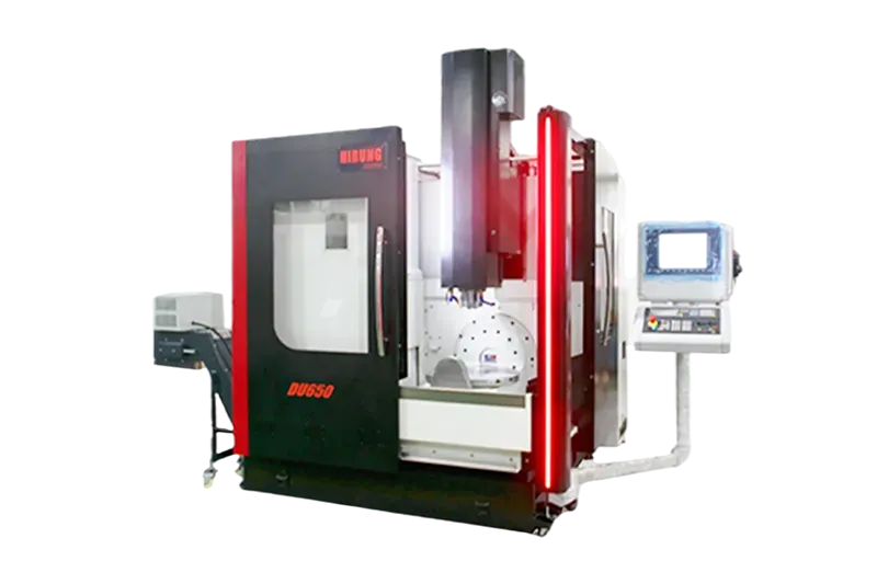
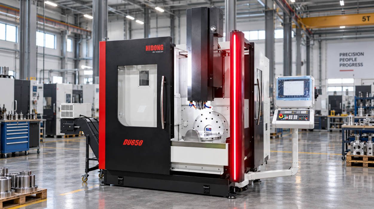
Aerospace impellers and blisks (integrally bladed rotors) operate under extreme centrifugal, aerodynamic, and thermal stresses. Manufacturing these rotating components demands uninterrupted aerodynamic curvature, thin-blade stiffness, and strict rotational balance. Traditional 3-axis or indexed 4-axis milling cannot navigate the narrow, deeply twisted flow channels of these designs without causing tool collisions or requiring multiple setups that introduce stack-up errors.
Modern multi-axis continuous milling directly addresses these constraints. Using continuous 5-axis CNC machining, machine spindles and rotary tables coordinate along five degrees of freedom simultaneously. This kinematic control allows cutting tools to maintain ideal engagement angles, eliminate tool-shank interference, and machine complex free-form surfaces in a single setup.
This guide evaluates the structural demands of blisks and impellers, the kinematic mechanics of 5-axis toolpaths, vibration control on thin-walled airfoils, machining strategies for aerospace superalloys, and practical criteria for evaluating a precision manufacturing partner.
The Geometry Challenge: Why Modern Impellers and Blisks Push Traditional Machining to Its Limits
Modern aerospace propulsion and turbomachinery increasingly rely on integrally bladed rotors (blisks) and high-efficiency impellers instead of conventional assemblies where discrete blades slot into a central disk via dovetail roots. Integrating the hub and aerodynamic blades into a single monolithic component yields significant weight reductions and eliminates aerodynamic leakage at blade attachment joints.
However, monolithic integration shifts assembly complexity into machining complexity:
- Extreme Spatial Curvature: Impeller flow channels twist across compound radii. Adjacent blades form narrow, converging throat areas where line-of-sight access from standard Cartesian axes is impossible.
- Deep Cavity Access: Hub surfaces sit deep within the channels, requiring long tools if cut perpendicularly. Conventional setups lead to tool deflection or catastrophic holder collisions.
- Thin-Walled Elasticity: As blade thicknesses taper toward trailing edges, workpiece rigidity drops. Cutting pressures easily induce chatter, blade deflection, and dimensional variance.
- Strict Dynamic Balancing: Rotors operating at high RPM cannot tolerate datum misalignment. Multi-setup milling transfers cumulative clamping errors directly into static and dynamic unbalance.
| Attribute | Conventional Assembled Rotor (Bladed Disk) | Monolithic Blisk / Integrally Bladed Rotor |
|---|---|---|
| Structural Integrity | Mechanical joints (dovetail/fir-tree slots) prone to fretting fatigue | Continuous grain and monolithic geometry; eliminates root fretting |
| Component Weight | Heavier due to root lugs and retention hardware | Up to 20% to 30% lighter depending on design parameters |
| Aerodynamic Efficiency | Subject to boundary layer disturbance at root interfaces | Smooth transitional fillets maximize laminar airflow |
| Machining Challenge | Simple individual blade profiling + broached disk slots | Highly complex simultaneous multi-axis milling of deep, crowded channels |
| Toolpath Access | Open access for individual blade fixturing | Severe spatial collision risks between cutter, arbor, and adjacent blades |
Overcoming these spatial and structural barriers requires specialized manufacturing workflows, specifically high-precision 5-axis CNC machining solutions capable of dynamic real-time orientation.
Core Kinematic Advantages: How 5 Continuous Axes Solve Critical Machining Bottlenecks
A 5-axis machining center introduces two rotary axes (commonly A and C on a trunnion table, or B and C on an articulating spindle head) alongside standard X, Y, and Z linear axes. In blisk and impeller production, simultaneous 5-axis interpolation changes tool engagement geometry in two primary ways:
Eliminating Tool Interference in Narrow, Curved Flow Channels
In a closed or semi-open impeller channel, the clearance between the suction side of one blade and the pressure side of the adjacent blade is often narrower than standard tool holder dimensions.
Simultaneous 5-axis control continuously tilts the tool axis relative to the workpiece normal vector. By dynamically swiveling the tool or tilting the workpiece, the machine maneuvers around blade overhangs, allowing tapered end mills or barrel cutters to machine the blade root and hub floor without the arbor contacting the blade tip.
Optimizing Tool Contact Angles and Effective Cutting Speeds
When a ball-nose cutter operates in a 3-axis orientation on a shallow contour, the center of the tool tip touches the workpiece. At the exact center of rotation, the cutting speed (Vc) approaches zero:
Vc=1000π⋅Deff⋅n≈0(when effective diameter Deff→0)
Zero surface speed scrapes rather than shears metal, generating elevated cutting heat, localized work-hardening, and poor surface texture. Through continuous five-axis orientation, the tool tilts at a prescribed lead/lag angle (often 10° to 20° depending on channel geometry). This shifts the contact zone away from the stationary tip to the tool’s fluted periphery, stabilizing the material removal rate (MRR) and improving surface finish.
Implementing advanced 5-axis CNC machining also allows the use of barrel and circle-segment cutters. Because barrel cutters present an exceptionally large profile radius along their cutting edge, step-over distances can be widened significantly while producing smaller cusp heights (scallops) than standard ball-end mills, reducing overall cycle times.
Tackling Deflection and Flutter: Maintaining Tolerances on Thin-Walled Aerodynamic Blades
Aerospace blades must feature knife-thin leading and trailing edges to maximize compression and aerodynamic efficiency. However, thin sections have very low bending stiffness. When subjected to cutting forces (Fc), the blade bends away from the cutter:
δ≈3⋅E⋅IFc⋅L3
Where δ\deltaδ is deflection, LLL is blade height, EEE is elastic modulus, and III is area moment of inertia.
Excessive deflection leads to taper errors, wall-thickness variations, and aerodynamic flutter during machining. Five-axis milling mitigates these physical errors through structured toolpath and setup strategies:
1. Minimal Tool Overhang
Because the machine tilts to access deep cavities, cutting tools can be configured with the shortest practical gauge length. Minimizing tool overhang maximizes tool assembly rigidity (k∝1/L3), reducing chatter marks across thin surfaces.
2. Synchronized Blade-Flank Machining (Point Milling vs. Flank Milling)
- Point Milling: Uses the tip radius of a ball or barrel cutter to generate surfaces via successive passes. It suits complex, double-curved non-developable ruled surfaces where blade torsion prevents continuous line contact.
- Flank (Swarf) Milling: Aligns the tool’s lateral cutting edge tangent to the ruled blade surface in a single sweep. When blade geometry permits, flank milling reduces machining passes and distributes lateral loads evenly down the blade span, minimizing local localized flutter.
3. Single-Setup Datum Precision
Machining an impeller across separate operations introduces datum transfer errors between the bore, back-face, and blade profiles. Simultaneous 5-axis milling machines the hub contour, flow channel, blade pressure faces, suction faces, and outer diameters in a single clamping phase. This preserves concentricity and true position within tight geometric tolerances, reducing post-machining dynamic balancing corrections.
Machining Difficult Aerospace Alloys: Thermal and Tool-Wear Dynamics
Aerospace blisks and impellers run in high-pressure, high-temperature engine zones, requiring alloys that retain structural properties near their melting points. These materials introduce specific machining challenges:
- Titanium Alloys (e.g., Ti-6Al-4V): Low thermal conductivity (k≈6.7 W/m⋅K) causes up to 80% of cutting heat to concentrate directly at the tool cutting edge. Titanium’s low modulus of elasticity also promotes workpiece spring-back.
- Nickel-Based Superalloys (e.g., Inconel 718): Contain abrasive carbide phases and exhibit extreme work-hardening tendencies during shear deformation, causing rapid notch wear and depth-of-cut grooving on tools.
| Material | Primary Machining Bottleneck | 5-Axis Toolpath & Process Solution |
|---|---|---|
| Ti-6Al-4V (Titanium Grade 5) | Extreme cutting-zone temperature; chemical affinity causing galling and built-up edge (BUE) | Through-spindle high-pressure coolant (HPC) directed at tool tip; continuous tilt maintains uniform chip load; climb milling to dissipate heat into chips. |
| Inconel 718 | High mechanical shear strength; rapid work-hardening; severe abrasive tool wear | Trochoidal roughing to prevent corner dwell; high-rigidity toolholders (shrink-fit/hydraulic); rigid multi-axis orientation prevents micro-vibrations that accelerate edge chipping. |
| Aerospace Aluminum (e.g., 7075-T6) | Built-up edge at high speeds; thin-web warping from internal residual stress | High-speed spindle dynamics (>18,000 RPM); balanced stage-machining (alternating sides of blades to release symmetrical stress); polished flute cutters. |
Note: Specific cutting feeds, speeds, and coolant pressures should be qualified against the specific alloy grade, heat-treatment state, and tool geometry.
When machining heat-resistant materials, 5-axis milling services for difficult alloys must combine rigid machine structures, synchronized spindle cooling, and verified multi-axis CAM strategies to maintain both tool life and surface integrity.
Technical Evaluation: What Engineers and Buyers Must Verify in a 5-Axis Manufacturing Partner
Selecting a manufacturing partner for aerospace-grade impellers and blisks requires auditing technical capabilities well beyond basic equipment ownership. B2B buyers and lead engineers should verify the following capabilities:
1. Machine Kinematics and Volumetric Accuracy
Evaluate machine design relative to workpiece dimensions:
- Trunnion / Swivel Table (C on A/B): Ideal for compact to medium-diameter impellers. Offers high rotational dynamics and wide tilt clearance.
- Articulating Spindle Head with Rotary Table (B-axis head, C-axis table): Better suited for large-diameter blisks where heavy rotor blanks would introduce excessive inertia on a full trunnion bed.
- Inquire whether the facility utilizes direct-drive rotary motors, optical glass scales, and periodic kinematic compensation (such as Renishaw AxiSet or manufacturer volumetric calibration cycles).
2. CAM Simulation and Digital Twin Capabilities
Five-axis continuous trajectories risk rapid, complex collisions between spindle housings, fixturing, and the workpiece. A capable supplier must demonstrate:
- G-Code Driven Verification: Simulation based directly on post-processed machine G-code (e.g., VERICUT) rather than internal CAM source code.
- Cutter Gouge and Holder Collision Avoidance: Automated multi-axis vector smoothing to prevent erratic machine axis deceleration in tight blend radii.
3. Metrology and Free-Form Coordinate Verification
Verifying complex free-form airfoils requires specialized metrology equipment:
- Continuous Scanning CMM: Coordinate Measuring Machines fitted with continuous contact analog scanning heads (or optical line scanners) to inspect profile error against native CAD surface files.
- Surface Topography Verification: Surface roughness testing across the entire blade span to confirm compliant micro-finish (Ra) values, ensuring component performance matches aerodynamic specifications.
Supplier Verification Matrix
| Audit Category | Verification Item | Technical Target / Specification | Pass/Fail Criteria |
|---|---|---|---|
| Machine Kinematics | Volumetric Calibration | Multi-axis kinematic compensation (e.g., AxiSet / laser interferometer cycles) | Real-time center of rotation offset compensation within tight volumetric limits |
| Coolant Delivery | Through-Spindle HPC | Minimum 70 bar (1000 psi) high-pressure delivery | Direct chip evacuation from deep channels without thermal thermal shock |
| CAM Processing | Controller-Matched Post-Processors | Dedicated multi-axis post-processors matched to machine kinematics | Smooth vector transition without erratic axis deceleration or jerk |
| Safety & Simulation | Digital Twin Verification | G-code level collision simulation (e.g., VERICUT) | Complete toolholder, spindle housing, and fixture envelope verified |
| Metrology | Free-Form Inspection | Multi-axis continuous scanning CMM or structured optical 3D scanning | Point-cloud overlay directly against native 3D CAD step/parasolid models |
| Quality System | Traceability & Standards | AS9100 / ISO 9001 certified aerospace quality management systems | Full material certs, tool wear logs, and dimensional verification records |
Key Takeaways
- Geometry Mastery: Continuous 5-axis CNC machining provides the rotational flexibility required to mill deep, narrow, and twisted flow channels on impellers and blisks without tool interference.
- Dynamic Surface Speed: Tilting the tool relative to the surface normal eliminates zero-velocity center cutting on ball mills, improving blade surface finish and cutting stability.
- Deflection Mitigation: Short tool overhangs and optimized point- or flank-milling toolpaths control blade flutter and chatter marks across thin-walled sections.
- Process Consolidation: Performing all profiling passes in a single setup preserves geometric concentricity and minimizes balancing corrections on high-speed rotating parts.
- Audit Priorities: When sourcing components, evaluate the supplier’s volumetric machine calibration, G-code collision simulation workflows, and non-contact/scanning CMM verification capabilities.
Frequently Asked Questions (FAQ)
What is the primary difference between machining an open impeller and a closed/shrouded impeller?
An open impeller features exposed blades that are accessible from the top and sides, allowing standard continuous 5-axis toolpaths to profile the blades and hub. A closed (shrouded) impeller features an integrated cover plate over the blade tips, creating fully enclosed internal flow tunnels. Closed impellers require specialized small-diameter cutters with extended reach, specialized EDM (electrical discharge machining), or multi-axis machining through narrow throat ports before final assembly or welding.
Can 5-axis CNC machining completely eliminate the need for manual blade polishing?
Modern 5-axis CNC milling with circle-segment (barrel) cutters, high-speed spindles, and optimized toolpaths can achieve surface finishes down to Ra 0.8–0.4 µm (32–16 µin) on many materials, which often satisfies aerodynamic specifications directly from the machine. While ultra-high-pressure stages may still require automated abrasive flow machining (AFM) or micro-blasting, high-precision 5-axis milling eliminates the dimensional inconsistency of manual hand-blending.
Why is single-setup 5-axis milling critical for rotational dynamic balancing?
When an impeller is repositioned across multiple fixtures, clamping variations and reference datum offsets introduce slight concentricity and axial runout deviations. At operational speeds exceeding 20,000–50,000 RPM, even minute eccentric mass distributions generate high centrifugal forces that cause severe bearing vibration. Single-setup 5-axis machining cuts the bore, hub, and blade profiles relative to a single coordinate system, minimizing residual dynamic unbalance.