When planning a multi-axis manufacturing workflow, deciding between simultaneous 5-axis vs 3+2 positional setups dictates equipment expenditure, toolpath complexity, cycle time, and component accuracy. Continuous contouring is mandatory only when a tool must constantly alter its orientation relative to the workpiece during the cut to clear interference or maintain contact along complex, non-developable surfaces. For prismatic components, deep cavities, and multi-sided hole patterns, 3+2 positional machining is typically more rigid, less expensive, and faster to program.
This guide analyzes the kinematic differences, physical tradeoffs in rigidity and metal removal rates, geometric boundaries, and operational software costs between both modes to help engineering and procurement teams choose the correct process.
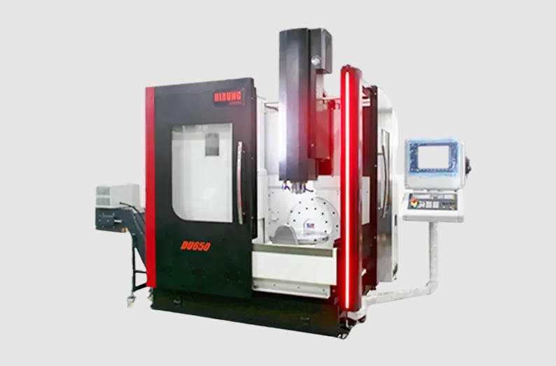
Beyond the Hype: True Simultaneous 5-Axis vs. 3+2 Positioning
In precision production, many components marketed as “5-axis machined” never require continuous rotary motion during cutting. Instead, they leverage five axes across distinct, sequentially locked orientations.
- 3+2 Positional Machining (Indexed 5-Axis): The two rotary axes orient the cutting tool to a specified compound angle. Once oriented, the rotary drives clamp shut mechanically, and the machine executes standard 3-axis milling routines along linear axes (X, Y, Z). The rotary axes do not move while the cutting tool engages the material.
- Simultaneous 5-Axis Machining (Continuous Contouring): All three linear axes and both rotary axes move synchronously under active computer control. The tool center point and tool orientation vector adjust dynamically throughout the cut.
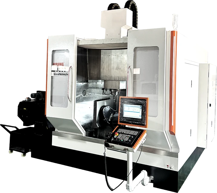
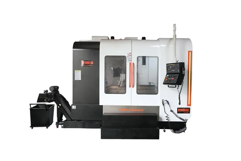
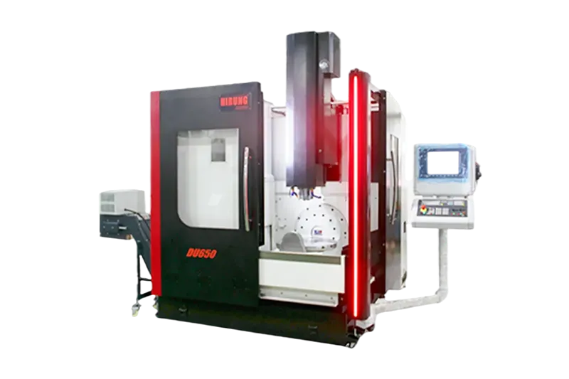
Confusing these two methods creates costly manufacturing misalignments. Specifying continuous 5-axis machining on components that only require positional indexing inflates machine-hour rates, increases collision risks, and demands unnecessary CAM post-processing steps. Modern workshops utilize advanced 5-axis CNC machining solutions to run both operational modes, but knowing which kinematic profile fits the geometry determines operational profitability.
Kinematic Differences: How Tool Movement and Control Loops Diverge
The fundamental distinction between continuous contouring and positional machining lies in how the CNC controller manages the tool vector relative to part coordinate systems.
3+2 Machining: Multi-Sided Indexing with Locked Rotational Axes
In 3+2 positional setups, work coordinate systems (WCS) are translated and tilted using controller cycles (such as G68.2 tilted work plane or PLANE SPATIAL functions). The rotary axes position the table or spindle head, after which hydraulic, pneumatic, or mechanical brakes engage to lock the rotary tables.
Because the rotary axes remain stationary during cutting, the machine tool functions as a high-rigidity 3-axis mill operating in tilted space. The CNC controller processes conventional 3-axis toolpaths (lines and circular arcs) without calculating dynamic machine geometry or tracking pivot points in real time.
Simultaneous 5-Axis: Continuous Dynamic Contouring
Continuous 5-axis machining demands that the CNC system continuously calculate the physical position of the cutting edge relative to the workpiece. Because rotating a table or swivel head moves the workpiece relative to the spindle nose, the controller must calculate real-time kinematics.
This process relies on Tool Center Point Management (TCPM / RTCP). As rotary axes pivot dynamically to tilt the tool away from workpiece shoulders or maintain constant surface contact, the linear drives accelerate and decelerate continuously to compensate for the rotational offset.
| Kinematic / Operational Factor | 3+2 Positional Machining | Simultaneous 5-Axis Contouring |
| Rotary Axis State During Cutting | Mechanically locked / clamped | Continuously interpolating |
| Active Axis Interpolation | 3 axes (X, Y, Z) | 5 axes (X, Y, Z + 2 Rotary) |
| Kinematic Tracking (RTCP/TCPM) | Not required during cutting | Mandatory in real-time |
| Mechanical System Rigidity | High (augmented by rotary axis clamping brakes) | Dependent on dynamic rotary drive stiffness |
| Toolpath File Size & Density | Standard (G01/G02/G03 linear & arc records) | Very large (dense point-to-point 5-axis vectors) |
| Post-Processor Complexity | Moderate (planes and frame transformations) | High (linearization, singularity management, feedrate smoothing) |
Rigidity vs. Flexibility: The Hidden Performance Trade-Offs
A common misconception is that simultaneous 5-axis machining is always technically superior to 3+2 operations. In structural and heavy roughing applications, continuous contouring can introduce mechanical vulnerabilities that 3+2 avoids.
Why 3+2 Machining Often Wins in Heavy Roughing and Metal Removal Rates
Mechanical clamping brakes on rotary tables generate substantially higher holding torque than active direct-drive or worm-gear motors can resist under dynamic cutting forces. During heavy metal removal in tough alloys like titanium, nickel superalloys, or pre-hardened die steels, 3+2 setups provide superior dynamic stiffness.
Furthermore, positional machining allows operators to point the tool directly into deep pockets or steep ribs, enabling the use of short, stubby end mills with minimal tool overhang. Because tool deflection increases with the cube of length-to-diameter ratio ($L^3/D^4$), cutting with short tools in a 3+2 orientation eliminates chatter, prolongs carbide insert life, and enables aggressive chip loads.
Surface Finish and Dynamic Accuracy in Continuous Contouring
Continuous 5-axis contouring excels when generating continuous freeform profiles. In 3+2 machining, blending intersecting 3-axis toolpaths across adjacent indexed faces leaves witness marks or cusp mismatches caused by axis positioning tolerances and thermal growth.
Simultaneous 5-axis machining avoids indexing seams by maintaining continuous point contact with ball-nose, barrel, or lens cutters across entire curved topologies. However, dynamic surface accuracy depends heavily on machine acceleration, servo loop tuning, and rotary backlash. Any dynamic lag in the rotational drives translates directly into gouges, micro-scallops, or surface waviness on the finished workpiece.
Feature-Driven Selection: When Is Continuous 5-Axis Absolutely Required?
Selecting between these two methods should be determined by workpiece geometry, tool collision vectors, and draft continuity.
| Continuous Tool Orientation Change Required? | Typical Geometric Features | Recommended Machining Strategy | Engineering Justification & Advantages |
| No | Multi-sided prismatic faces, undercut planar surfaces, inclined compound holes, deep structural pockets | 3+2 Positional Machining | Maximizes mechanical rigidity via locked axis brakes, permits short and stubby cutting tools, shortens CAM programming cycles, and reduces machine-hour rates. |
| Yes | Non-developable freeform surfaces, twisted channels, continuous variable-draft sidewalls, organic aerodynamic contours | Simultaneous 5-Axis Machining | Prevents tool holder interference in enclosed profiles, enables continuous vector control via dynamic RTCP/TCPM, and eliminates blend lines on continuous curved faces. |
Geometries That Mandate Full Simultaneous Contouring
Continuous 5-axis motion is non-negotiable when a cutting tool must constantly change its spatial lead and tilt angles to machine a feature without shank collision:
- Impellers, Blisks, and Turbomachinery Rotors: Twisted, overlapping aerodynamic blades create variable-width flow channels. A stationary tool axis cannot traverse from the hub to the shroud without colliding with adjacent blade edges.
- Deep Involute Porting and Manifolds: Complex intake manifolds and fluid channels that sweep in three dimensions require continuous tool orientation changes along the spline center line.
- Medical Implants with Organic Freeform Surfaces: Artificial knee components, femoral stems, and bone plates feature complex compound curvatures that require barrel cutters to maintain tangential contact across the geometry.
- Undercut Walls with Changing Drafts: Continuous sidewalls whose draft angle varies along the length of the toolpath cannot be segmented into fixed planes without leaving transition steps.
Typical Workpieces Ideal for 3+2 Positional Machining
For components that do not feature twisted, multi-dimensional surfaces, 3+2 provides a more reliable manufacturing route:
- Prismatic Housings and Gearboxes: Machining mounting faces, seal grooves, and precision dowel holes across 5 sides of an aluminum casting or billet.
- Deep Mold and Die Cavities: Indexing the core or cavity block to reach deep corner radii using short, rigid tools.
- Complex Orthogonal Hole Patterns: Drilling, reaming, and tapping holes angled compoundly relative to datum faces, where rigid drilling cycles require high axial thrust.
Operational Bottlenecks: Programming Overhead, Collision Risks, and Licensing
The transition from positional machining to continuous 5-axis introduces logistical and technical overhead across the shop floor.
| Workflow Stage | 3+2 Positional Machining Setup | Simultaneous 5-Axis Contouring Setup |
| Plane & Vector Definition | Define local tilted work plane (e.g., G68.2 / PLANE SPATIAL) | Calculate continuous surface normals and dynamic tool vectors |
| Toolpath Planning | Conventional 2.5D/3D pocketing, contouring, and drilling | Multi-axis flank milling, point-vector interpolation, and lead/tilt smoothing |
| Kinematic Risk Management | Standard static clearance checks | Active singularity avoidance and rotary axis reversal mitigation |
| Simulation & Verification | Standard CAD/CAM internal verification | Full G-code-driven digital-twin kinematic machine simulation |
| CNC Execution | Standard axes motion with rotary brakes clamped | Dynamic RTCP/TCPM interpolation across all 5 axes |
- CAM Software Licensing: Basic 3+2 indexing toolpaths are supported in entry-level 3-axis CAM packages. True continuous 5-axis toolpath generation—such as multi-axis flank milling, point-vector interpolation, and rotary axis singularity management—requires advanced CAM tiers and specialized multi-axis software extensions.
- Kinematic Singularities: When the tool axis aligns parallel with a machine’s rotational axis (such as reaching 0° on a B-axis swivel head), a “singularity” occurs. At this point, the secondary rotary axis must theoretically spin 180 degrees instantaneously to maintain toolpath continuity, causing rapid axis movements and surface gouging unless CAM software decelerates feedrates or applies vector smoothing.
- Collision Verification: While 3+2 allows basic static clearance checks, continuous contouring demands complete G-code-driven digital twin simulation. The moving kinematics of trunnion tables, spindle castings, tool holders, and fixtures must be calculated millisecond by millisecond to prevent catastrophic collisions during rapid positioning and simultaneous feed motion.
The 5-Axis Selection Framework: How to Evaluate Your Parts and Budget
Use this structured decision framework to determine whether a given part should be routed to 3+2 or continuous contouring:
- Assess Surface Developability: Can the geometry be divided into planar faces, ruled features, or isolated pockets? If yes, route to 3+2 positional machining to minimize cycle time and programming risk.
- Evaluate Tool Access and Clearance: Can standard tools reach every feature when tilted at fixed angles? If tool shank or holder interference occurs regardless of tilt angle, simultaneous contouring is mandatory to continuously sweep around obstacles.
- Analyze Tolerance and Blending Requirements: If a curved transition spans multiple faces and demands tight surface tolerances ($Ra < 0.8\ \mu\text{m}$), simultaneous contouring eliminates the hand-polishing and witness lines associated with 3+2 toolpath overlaps.
- Account for Machine Availability and Cost: Operating costs for dedicated continuous 5-axis platforms are generally higher than 3+2 machines due to initial machine investment, sophisticated feedback scales, and dynamic rotary wear. Maximize 3+2 indexing to reserve continuous machine hours for parts that require full kinematic flexibility.
When engineering complex components, reviewing designs with experienced 5-axis CNC machining specialists ensures the chosen strategy yields optimal geometric tolerances at the lowest viable unit cost.
Frequently Asked Questions (FAQ)
Can a simultaneous 5-axis machine perform 3+2 positional operations?
Yes. Nearly all continuous 5-axis CNC machines can run 3+2 operations. In fact, production shops often run 3+2 positional operations on continuous 5-axis equipment for roughing cycles because clamping the rotary axes provides higher structural rigidity, allowing for heavier chip loads before finishing with continuous contouring.
Is continuous 5-axis machining always more expensive than 3+2?
In terms of hourly machine run rates, continuous 5-axis machining is typically more expensive due to higher capital costs, specialized CAM licenses, and slower feed rates required around kinematic singularities. However, for organic parts like impellers, attempting 3+2 indexing requires dozens of setups and extensive manual polishing, making continuous contouring more cost-effective overall.
Does 3+2 machining eliminate the need for multi-axis CAM software?
In many cases, yes. Most standard CAD/CAM platforms include 3+2 indexing functionality (planar frame indexing or tilted work planes) within baseline tiers. Continuous 5-axis operations require advanced multi-axis modules to calculate surface normal leads, tilt angles, and collision-avoidance vectors.
How does continuous 5-axis machining compare to 3+2 for tool life?
Tool life depends on cutting dynamics. 3+2 machining generally provides superior tool life during roughing because the shorter, clamped tool setup minimizes chatter and deflection. However, on steep or curved walls, continuous 5-axis contouring maintains constant cutting engagement and chip load across the tool profile, preventing uneven tip wear and premature carbide chipping.
Key Takeaways
- The Core Difference: 3+2 machining locks rotational axes at fixed angles during cutting; simultaneous 5-axis interpolates all five axes synchronously under active RTCP/TCPM management.
- Rigidity Advantages: 3+2 machining engages mechanical axis brakes, providing superior dynamic stiffness and allowing shorter, more rigid tools during heavy roughing.
- When Continuous Is Mandatory: Aerodynamic blisks, impellers, medical implants with complex organic contours, and continuously variable draft undercut walls require simultaneous motion to avoid tool collisions.
- Cost and Complexity: Simultaneous machining demands higher-tier CAM software, digital-twin collision verification, and careful singularity management, translating to higher machine-hour rates.
- Production Rule: Never use continuous 5-axis contouring if the part can be oriented and cleared using 3+2 indexing.