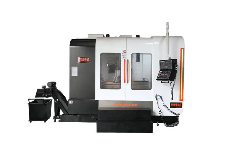
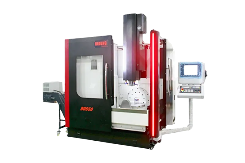
In simultaneous 5-axis CNC machining, controlling tool orientation through lead and tilt angles shifts the cutting contact zone away from the dead center of a ball nose end mill, preventing zero-velocity rubbing and improving surface finish. Selecting the proper angle configuration depends on workpiece geometry, tool holder clearance, rotary axis kinematics, and material machinability. While our guide to choosing 5-axis toolpath strategies by part type works one level up, this article goes deeper into a single variable: how the tool axis is steered, and what that steering does to cutting mechanics and machine dynamics. The same principles apply across HIRUNG’s simultaneous 5-axis machining centers, from trunnion-style table-table machines to swivel-head designs.
Defining Lead and Tilt Angles in Simultaneous 5-Axis Machining
Lead and tilt angles define the orientation of the cutting tool axis relative to the workpiece surface normal and the instantaneous feed direction. Unlike indexed 3+2 positioning—where rotary axes lock at fixed angles before cutting—simultaneous 5-axis toolpaths continuously adjust these angles along every point of the trajectory.
To program tool orientation accurately in CAM software, engineers rely on a local coordinate frame anchored at the cutter contact point:
- Surface Normal: A vector perpendicular to the machined surface at the exact point of contact. A 0° lead and 0° tilt orientation aligns the tool axis directly with this vector.
- Feed Direction: The tangent vector pointing along the forward travel path of the cutting tool.
- Lead Angle: The rotation of the tool axis forward or backward within the plane formed by the surface normal and the feed direction. A positive lead angle inclines the tool forward in the direction of travel, while a negative lead angle (drag angle) leans the tool backward against the feed direction.
- Tilt Angle: The rotation of the tool axis sideways—perpendicular to the feed direction—to the left or right of the toolpath.
| Parameter | Lead Angle | Tilt Angle |
|---|---|---|
| Reference Axis of Rotation | Transverse axis (perpendicular to both feed direction and surface normal) | Feed direction vector (tangent to the toolpath) |
| Direction of Inclination | Forward (positive) or backward (negative) along the cutting path | Sideways (left or right) relative to the cutting path |
| Primary Objective | Eliminate zero cutting speed at the ball tip and optimize chip evacuation | Clear adjacent walls, ribs, or fixtures and improve tool holder access |
| Primary Collision Risk | Leading or trailing edge gouging on concave surfaces with tight radii | Lateral interference between the tool holder/spindle and steep pocket walls |
Why Tool Orientation Matters: Overcoming the Ball Nose “Dead Center” Problem
When a ball nose end mill cuts perpendicular to a surface (0° lead and 0° tilt), the exact center tip of the tool touches the workpiece. Because the rotational radius at the center tip is zero, the surface cutting speed (Vc) drops to zero at that contact point.
Without rotational cutting velocity, the center flutes cannot shear the material cleanly. Instead, the tool tip plows and extrudes the metal, generating localized friction, excessive heat, and work hardening. This mechanical rubbing causes premature edge chipping, degraded surface roughness, and inconsistent dimensional accuracy across contoured surfaces.
Applying a controlled lead or tilt angle resolves this issue through four direct mechanical changes:
- Increasing Effective Cutting Diameter: Tilting the tool moves the contact point onto the spherical flank of the cutter, where the rotational radius is larger. Depending on the cutter diameter and angle applied, this increases the actual surface speed at the cut zone and restores true shearing action.
- Improving Chip Formation and Evacuation: Engaging the side flutes creates a cleaner chip thickness profile and opens space ahead of the cut for coolant or air blast to clear chips before re-cutting occurs.
- Reducing Axial Thrust Forces: Perpendicular cutting concentrates forces directly up the spindle axis, promoting chatter and vibration on thin walls unless the machine structure is built to damp them. Inclining the tool redirects cutting forces into radial components that the cutter flutes are designed to handle efficiently.
- Expanding Stepover Efficiency with Bull Nose Cutters: When using torus (bull nose) end mills on shallow contours, a small positive lead angle allows the corner radius to sweep a wider effective path, reducing cusp height without requiring ultra-fine stepovers.
How to Select and Optimize Lead and Tilt Angles for Different Geometries
Selecting between a fixed angle, a variable interpolated angle, or a combined lead-and-tilt strategy requires evaluating how the local surface curvature interacts with the tool assembly. Over-tilting an open surface wastes rotary axis motion, whereas under-tilting inside a deep cavity risks catastrophic holder collision.
| Part Geometry Feature | Recommended Orientation Strategy | Primary Engineering Goal | Key Programming Consideration |
|---|---|---|---|
| Open Freeform Surfaces | Fixed positive lead angle (typically a moderate forward incline, verified against surface radius) | Maintain constant effective cutting speed and uniform surface texture | Verify that the trailing heel of the cutter does not gouge concave curvature transitions |
| Deep Cavities and Steep Walls | Lateral tilt angle away from the adjacent wall, combined with a slight positive lead | Maximize tool holder clearance and allow shorter, more rigid tool stick-out | Monitor rotary axis limits as the tool transitions around internal corners |
| Impeller Blades and Blisks | Variable interpolated lead and tilt angles guided by hub and shroud drive surfaces | Prevent collisions between neighboring blades while maintaining smooth flow-line finishes | Smooth angular transitions across the blade leading and trailing edges to avoid dwell marks |
| Undercuts and Reverse Drafts | High tilt angle or negative lead configurations matched to the undercut vector | Reach obstructed features in a single setup without custom form tools | Validate full spindle and fixture envelopes using machine-level kinematic simulation |
For open sculpted surfaces—such as aerospace structural skins or mold cavities—a fixed positive lead angle generally delivers the most consistent surface finish, because the rotary axes remain relatively stationary while the linear axes drive the feed. That is the same mechanism behind continuous tool contact on curved surfaces: instead of re-clamping the part into new orientations, the tool axis follows the geometry while the contact point stays on the active flank of the cutter.
Conversely, complex multi-blade components such as impellers and blisks require variable (interpolated) lead and tilt angles so the CAM system can continuously steer the tool shank clear of adjacent blades. This is the workload the DC series was configured for on aerospace geometries: continuous axis interpolation with collision-verified, flow-line finishing between closely spaced blades.
Engineers should generally avoid negative lead angles (drag angles) during standard finishing passes. Leaning the tool backward forces the center tip closer to the uncut stock and traps chips beneath the cutting edge, unless specific geometric constraints at a pocket exit temporarily require a negative tilt to clear an overhang.
Balancing Tool Orientation with Machine Kinematics and Collision Avoidance
An ideal tool angle in CAM software can still produce poor results on the shop floor if it exceeds the physical and dynamic limits of the CNC machine tool. Effective tool axis control requires balancing cutting geometry against real machine kinematics. Use the following engineering verification checklist before releasing a simultaneous 5-axis program to production:
- Tool Holder and Spindle Clearance: Check the entire assembly—including the collet nut, shrink-fit holder, and spindle nose—against the workpiece, clamps, and rotary table. Angling the tool away from steep walls often lets machinists use a shorter tool stick-out, which substantially increases rigidity and reduces deflection.
- Rotary Axis Velocity and Acceleration Limits: Heavy trunnion tables and swivel heads have lower maximum angular velocities and accelerations than linear X/Y/Z ballscrews, which is why DU-series trunnion machines and DV-series direct-drive swivel-head machines are matched to different part families. Sharp changes in lead or tilt angles force the controller to throttle linear feed rates so the rotary axes can catch up, leaving visible dwell marks on the part.
- Singularity Zone Avoidance: On table-table or head-head 5-axis configurations, a kinematic singularity occurs when the tool axis passes directly through or near the pivot center of the rotary axes (such as A-axis or B-axis near 0°). In this zone, microscopic variations in surface curvature can trigger a sudden 180° C-axis rotation. Applying a slight constant lead or tilt bias keeps the toolpath safely outside the singularity cone.
- Tool Center Point Management (RTCP / TCPM): Confirm that the post-processor outputs proper dynamic tool length compensation codes so the controller automatically compensates for pivot-point offsets as lead and tilt angles change during the cut. This capability is detailed in the RTCP and look-ahead section of our 5-axis specification guide.
When evaluating suppliers for simultaneous 5-axis CNC machining, confirming that their engineering team performs full machine-kinematic simulation before releasing a program—not just basic toolpath verification—helps prevent unexpected cycle-time delays and surface blemishes on complex parts.
Troubleshooting Common Tool Orientation Issues in 5-Axis Milling
Even well-structured toolpaths can exhibit surface defects or tool wear issues if lead and tilt parameters do not match the material behavior or machine dynamics. The table below outlines common machining symptoms tied to tool orientation and how to correct them.
| Observed Machining Defect | Root Cause in Tool Orientation | Corrective Action |
|---|---|---|
| Dull, smeared, or burnished band along the cut path | Lead or tilt angle is too small, allowing the zero-velocity center tip of the ball end mill to rub the material | Increase the positive lead angle to shift the contact point onto the active side flutes |
| Visible step marks or dwell lines across smooth contours | Rapid fluctuations in lead/tilt angles exceeding rotary axis acceleration limits | Apply angle smoothing filters in CAM, widen interpolation tolerances, or switch to a fixed lead angle |
| Gouging or over-cutting in concave fillets | Excessively large positive lead angle causing the back edge of the tool radius to contact the steep concave slope | Reduce the lead angle in tight concave regions or match the cutter radius to the minimum fillet radius |
| Sudden C-axis spin and surface gouge near flat peaks | Toolpath crossing a machine kinematic singularity zone at near-perpendicular orientation | Add a constant 3°–5° lead or tilt bias to steer the rotary axes away from the 0° pole |
| Excessive chatter and rapid flank wear on deep walls | Tool orientation forces the use of an overly long tool assembly due to insufficient lateral tilt | Increase the tilt angle away from the wall to gain holder clearance and shorten tool overhang |
Key Takeaways
- Preventing Zero-Velocity Cutting: Tilting a ball nose end mill via a positive lead angle shifts contact away from the zero-speed center tip onto the active flutes, replacing material rubbing with clean shearing.
- Distinct Geometric Roles: Lead angles incline the tool forward or backward along the feed direction to optimize cutting mechanics, while tilt angles lean the tool sideways to clear adjacent walls and fixtures.
- Kinematics Over Pure Geometry: Excessive or abrupt angular changes trigger rotary axis deceleration, dwell marks, and kinematic singularities; smooth angle interpolation is essential for consistent surface finish.
- Rigidity Through Clearance: Strategic lateral tilt angles allow programmers to clear deep pocket walls using shorter, more rigid tool assemblies, reducing chatter and deflection.
- Drawing Specifications for Outsourcing: B2B buyers do not need to dictate CAM lead/tilt values on prints; specifying accurate surface profile tolerances and surface finish requirements allows the machining supplier to optimize tool orientation for their equipment.
Frequently Asked Questions About Lead and Tilt Angles
What is a typical starting lead angle for ball nose end mills in 5-axis machining?
A moderate positive lead angle of 10° to 15° is commonly used as an initial baseline for ball nose finishing on open contours. The exact optimal angle depends on the cutter diameter, axial depth of cut, material hardness, and minimum concave radius of the part, and should be verified through CAM collision checking.
Can lead and tilt angles be used simultaneously on the same toolpath?
Yes. Combining lead and tilt angles creates a compound tool orientation that simultaneously eliminates dead-center rubbing along the feed direction and tilts the tool holder away from lateral obstructions. CAM systems calculate this compound vector automatically when both parameters or wall-avoidance constraints are active.
How does tool orientation affect cycle time in simultaneous 5-axis milling?
Increasing the lead angle enlarges the effective cutting diameter, which permits higher spindle speeds or wider stepovers and can shorten machining time. However, aggressive or erratic angular changes force the machine controller to decelerate linear feed rates to stay within rotary axis speed limits, which increases overall cycle time.
Do buyers need to specify lead and tilt angles on engineering drawings when outsourcing 5-axis parts?
No. Engineering drawings should define functional part requirements—such as dimensional tolerances, surface profile callouts, datum references, and target surface roughness—rather than CAM programming parameters. Qualified manufacturing partners determine the appropriate lead, tilt, and tooling strategies based on their specific machine kinematics and process setup.