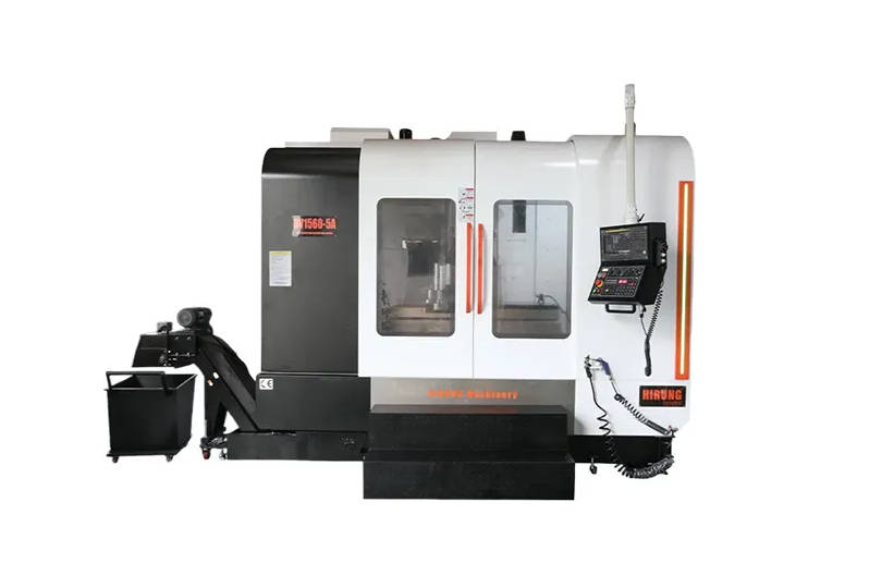
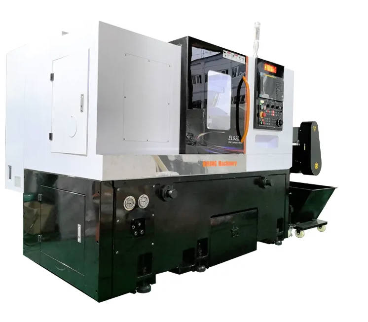
Selecting the right toolpath strategy in 5-axis CNC machining depends directly on the target part’s geometric features, material machinability, and tolerance requirements. Rather than defaulting to full simultaneous motion for every complex component, effective 5-axis CAM programming matches specific toolpath algorithms—such as 3+2 positional indexing, swarf cutting, flowline finishing, or multiaxis roughing—to individual surface and cavity geometries.
When evaluating how to program a multi-axis part, engineers and technical buyers must balance three core variables: tool rigidity, cycle time, and collision clearance. Applying simultaneous motion where simple indexing suffices increases programming overhead and reduces cutting rigidity, whereas relying on fixed angles for continuous freeform surfaces leaves visible cusp marks and requires excessive hand polishing. This guide breaks down how to select optimal 5-axis milling toolpaths by part geometry, outlines key engineering variables that alter toolpath choices, and provides a Design for Manufacturability (DFM) checklist to streamline production.
3+2 Positional vs. Simultaneous 5-Axis: The First Decision in CAM Programming
The foundational step in 5-axis CAM programming is determining whether a feature requires 3+2 positional machining or simultaneous 5-axis machining. In 3+2 machining (also known as indexed 5-axis), the two rotary axes tilt and lock the workpiece into an optimal orientation before a standard 3-axis toolpath executes the cut. In simultaneous 5-axis machining, all three linear axes (X, Y, Z) and two rotary axes (A, B, or C) move continuously at the same time to maintain an ideal cutter orientation relative to the part surface. The kinematic and rigidity trade-offs between simultaneous 5-axis and 3+2 positioning determine which features tolerate indexed motion and which truly demand continuous contouring.
Choosing 3+2 positioning whenever geometry allows yields higher cutting rigidity because the rotary axes remain clamped during material removal. This enables the use of shorter, stiffer cutting tools, higher feed rates, and simpler post-processing. Simultaneous 5-axis motion should be reserved for geometries where continuous tool axis variation is physically required to reach the surface, maintain a constant chip load, or avoid tool-holder collisions.
| Evaluation Criteria | 3+2 Positional Machining | Simultaneous 5-Axis Machining |
|---|---|---|
| Axis Motion Type | Rotary axes lock in place; X, Y, Z cut simultaneously. | All 5 axes move continuously during cutting. |
| Tool Rigidity | High, due to clamped rotary brakes and shorter tool stick-out. | Moderate, dependent on rotary drive stiffness and dynamic load. |
| Programming Complexity | Lower; relies on standard 3-axis planar toolpaths per orientation. | Higher; requires continuous tool-axis vector control and collision verification. |
| Surface Finish Quality | Ideal for flat faces, pockets, and angled bores; leaves step transitions if blended across planes. | Superior for continuous organic contours and ruled walls without witness lines. |
| Typical Cost Impact | Lower programming time and faster cycle times on prismatic features. | Higher programming cost, justified when eliminating secondary setups or EDM. |
When partnering with a manufacturing supplier offering custom 5-axis CNC machining services, combining both approaches within a single program—using 3+2 strategies for heavy roughing and simultaneous toolpaths for critical curved surfaces—typically delivers the lowest total part cost.
Matching 5-Axis Toolpath Strategies to Specific Part Geometries
Different industrial geometries place distinct mechanical demands on the cutting tool and machine kinematics. Matching the CAM strategy to the specific part type prevents premature tool wear, chatter, and gouging.
Multi-Sided Prismatic Parts and Aerospace Housings: Index Milling and Hole Making
Multi-sided structural housings, manifolds, and avionics enclosures feature pockets, bosses, and compound-angle holes across five or more faces. Programming these parts primarily relies on 3+2 index milling paired with multi-axis drilling cycles.
- Short-Tool Tilting: Instead of using long-reach end mills to clear deep walls from a single top-down setup, CAM programmers tilt the workpiece to approach side pockets perpendicularly. Shorter tools reduce deflection and improve dimensional accuracy across perpendicular datums.
- Multi-Axis Hole Making: Angled lubrication ports and mounting holes are programmed using automated feature-recognition drilling cycles that orient the spindle normal to each hole axis, eliminating custom angle plates and multiple fixture setups—the same done-in-one setup consolidation that drives 5-axis labor savings.
- Rest Machining Across Planes: After roughing from multiple index angles, 3D stock models track remaining corner material so smaller finishing tools only cut unmachined zones rather than cutting air.
Impellers, Blades, and Ruled Surfaces: Swarf Cutting vs. Point Milling
Turbomachinery components, impellers, blisks, and structural aerospace ribs contain thin, twisted walls known as ruled surfaces. For these parts, the primary CAM decision lies between swarf cutting (flank milling) and multi-axis point milling—a workpiece class that machines such as the HIRUNG DC Series 5-axis machining center are specifically configured for.
- Swarf Cutting: The side (flank) of a tapered or cylindrical end mill contacts the entire height of the wall simultaneously, machining the surface in a single pass. Swarf cutting dramatically reduces cycle times and produces smooth, continuous grain along blades. However, it is strictly limited to developable ruled surfaces—geometries where a straight line can lie flat against the surface from top to bottom without twisting away from the cutter flank.
- Multi-Axis Point Milling: When blade geometry twists aggressively (non-developable surfaces) or features varying wall thicknesses, swarf cutting will gouge the middle of the blade or leave excess stock at the root. Point milling uses the tip of a ball-nose or bull-nose end mill to make multiple step-down passes along the surface, sacrificing cycle speed for exact geometric accuracy.
Complex Freeform Contours and Medical Components: Flowline and Geodesic Strategies
Orthopedic implants, prosthetic joints, and aerodynamic fairings consist of smooth, double-curved freeform surfaces where surface finish directly affects part performance and fatigue life. Standard 3-axis parallel raster toolpaths fail on these parts because stepover spacing stretches on steep vertical walls, leaving uneven ridges.
- Flowline Finishing: The CAM system generates toolpaths that follow the natural UV iso-curves of the CAD surface. By tilting the tool at a consistent lead angle (typically 10° to 15° forward in the direction of travel), the programmer keeps the center dead-zone of a ball-nose cutter off the workpiece, ensuring clean shearing action.
- Geodesic Toolpaths: When freeform surfaces consist of multiple stitched CAD patches with conflicting UV directions, geodesic strategies calculate equidistant paths across the entire composite surface. This maintains a uniform scallop height regardless of surface curvature or steepness.
Deep Mold Cavities and Narrow Ribs: Collision Avoidance and Tilt Control
Injection molds, die-casting inserts, and deep structural pockets present severe tool-holder collision risks and high length-to-diameter (L/D) ratios. Programming these geometries requires proactive tilt control and progressive roughing.
- Multiaxis Adaptive Roughing: Rather than plunging straight down into a deep cavity, the CAM strategy uses constant-engagement trochoidal or waveform paths while tilting the tool away from vertical walls. This maintains a consistent radial chip load and prevents heat spikes.
- Automatic Holder Collision Avoidance: Modern 5-axis finishing paths define the exact 3D geometry of the tool holder and spindle nose. As the cutter descends into a narrow rib, the CAM algorithm dynamically tilts the tool axis just enough to maintain a safe clearance gap between the holder and the cavity rim, minimizing required tool stick-out. This in-machine verification extends the multi-axis program verification and simulation workflow that should back every released 5-axis program.
Chatter Prevention Checklist for Deep Cavities
- Limit tool stick-out to the absolute minimum required for the maximum cavity depth plus clearance.
- Apply smooth angular smoothing (tool-axis filtering) so rotary axes do not jerk rapidly around tight internal corners.
- Use variable-helix end mills combined with a slight pull-angle (tilt away from the wall) to stabilize cutting forces.
Undercuts and Internal Ports: Lollipop Cutters and Multi-Axis Deburring
Internal fluid passages, O-ring grooves behind flanges, and reverse-draft features cannot be reached with standard straight end mills. Using lollipop cutters or T-slot cutters driven by simultaneous 5-axis toolpaths allows manufacturers to machine undercuts in the primary setup, avoiding costly Electrical Discharge Machining (EDM). Whether your machine can reach these features at all depends on rotary architecture—the tool access and collision risks of trunnion vs. swivel head configurations decide how deep and how steep an undercut each platform can actually finish.
For cross-drilled holes and sharp internal intersections, dedicated 5-axis deburring toolpaths trace edge loops automatically using spherical cutters. The CAM software tilts the tool continuously to keep the cutter shank clear of adjacent walls while breaking sharp edges to a controlled chamfer width.
Summary Matrix: Selecting the Right 5-Axis Toolpath at a Glance
The matrix below provides a quick-reference framework for matching common industrial part geometries to their corresponding CAM strategies, cutting tools, and primary engineering risks.
| Part Type | Primary Toolpath Strategy | Typical Tool Geometry | Key Programming Focus | Primary Risk to Manage |
|---|---|---|---|---|
| Multi-Sided Prismatic Housings | 3+2 Positional Roughing & Planar Finishing | Flat end mill, bull-nose end mill, indexable drills | Minimizing rotary index moves; datum alignment across faces | Cumulative angular positioning error if fixtures flex |
| Impellers, Blisks & Turbine Blades | Swarf Cutting (developable) or Multi-Axis Point Milling | Tapered ball-nose or conical end mill | Controlling lead/tilt angles; avoiding hub-to-blade root gouging | Thin-wall deflection and vibration during flank contact |
| Freeform Contours & Medical Implants | Flowline or Geodesic Simultaneous Finishing | Ball-nose or barrel (circle-segment) cutter | Constant scallop height; keeping ball tip center off the cut | Witness lines between adjacent CAD surface patches |
| Deep Cavities & Narrow Mold Ribs | Multiaxis Roughing + Collision-Avoidance Finishing | Long-neck bull-nose or tapered ball-nose cutter | Dynamic holder clearance; smooth rotary axis interpolation | Tool-holder collision and high-L/D chatter |
| Undercuts & Internal Fluid Ports | Simultaneous Curve/Surface Tracking & Auto-Deburring | Lollipop cutter, spherical mill, or T-slot cutter | Exact shank clearance verification inside enclosed volumes | Blind-spot gouging due to restricted line-of-sight |
4 Critical Factors That Override Geometry in 5-Axis CAM Planning
While part geometry dictates the baseline toolpath family, four real-world manufacturing variables frequently force CAM programmers to modify their strategy:
- Workpiece Material Machinability: A toolpath optimized for aluminum 6061 or 7075—which favors high spindle speeds and aggressive radial engagement—will rapidly destroy carbide tooling in titanium (Ti-6Al-4V) or nickel superalloys (Inconel 718). For heat-resistant alloys, programmers shift to high-feed, low-radial-depth dynamic milling strategies and strictly limit rapid tool-axis reversals that cause momentary dwell and work hardening. The same material-driven choice between high-speed and high-torque spindles applies to the machine side of this decision.
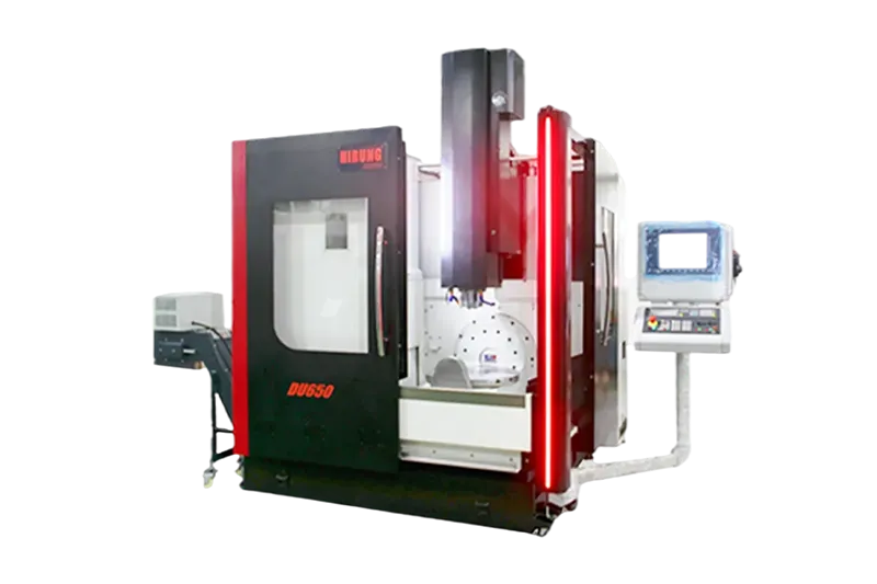
- Machine Kinematics and Singularity Limits: 5-axis machines utilize different rotary configurations—such as trunnion (table-table), swivel-head (head-head), or hybrid (head-table) designs—depending on the machine configuration. The kinematic difference between trunnion and swivel head architectures explains why the same program behaves differently across platforms: on a DU Series table-table trunnion machine the part rotates under a static tool, while a DV Series direct-drive swivel-head machine brings the tool around a stationary workpiece. When a toolpath passes directly through the rotary center point (the pole or singularity zone), rotary axes must spin 180 degrees instantaneously, causing surface gouges or feed-rate drops. Programmers must tilt the setup or adjust tool-axis limits to steer paths away from kinematic singularities.
- Cutter Geometry Advancements (Barrel Cutters): The introduction of circle-segment (barrel) cutters allows programmers to take much larger stepovers during simultaneous finishing than traditional ball-nose tools while achieving identical surface roughness. However, barrel cutters require specialized tangent-to-surface toolpath algorithms and exact contact-point control to prevent overcutting.
- Tolerance and Surface Roughness Specifications: Tight profile tolerances and low Ra surface requirements demand fine chordal tolerances (linearization accuracy) in the CAM output. Tightening chordal tolerance increases NC code size exponentially, requiring the machine controller’s look-ahead buffer to process thousands of micro-blocks per second smoothly without stuttering—one of the key factors that govern real 5-axis machining accuracy.
DFM Checklist: Preparing Your CAD Files for Efficient 5-Axis Programming
Design engineers can significantly reduce CAM programming hours, machining cycle times, and unit costs by reviewing their 3D models against manufacturing constraints prior to requesting a quote:
- Standardize Internal Corner Radii: Ensure internal vertical and floor fillets match standard cutter radii (plus a slight clearance allowance so the tool does not bury 100% into a corner and chatter).
- Limit Cavity Depth-to-Width Ratios: Keep pocket depths reasonable relative to corner radii so standard-length tools can reach the floor without requiring excessive holder tilting.
- Provide Clean, Solid B-Rep CAD Models: Supply native neutral formats such as STEP (.stp) or Parasolid (.x_t) with stitched, watertight surfaces rather than faceted STL meshes, which degrade smooth 5-axis tool-axis vector calculation.
- Specify Only Necessary Tight Tolerances: Reserve tight geometric tolerances (GD&T) for functional mating interfaces rather than applying blanket tight tolerances across non-critical freeform surfaces.
- Define Clear Datum Reference Frames: Establish accessible primary, secondary, and tertiary datums that remain reachable during 5-axis probing and final CMM inspection.
Working early with an experienced manufacturing partner helps catch tool-access bottlenecks before metal is cut. Reviewing your CAD geometry alongside HIRUNG’s 5-axis CNC machining capabilities ensures that part features align with practical cutter reach, fixture stability, and efficient toolpath execution—send your model for a machining feasibility review before the first chip is cut.
Key Takeaways
- Prioritize 3+2 Before Simultaneous Motion: Use 3+2 positional machining for flat faces, angled holes, and heavy roughing to maximize tool rigidity and reduce programming costs; reserve simultaneous 5-axis toolpaths for continuous freeform surfaces, twisted blades, and collision-restricted cavities.
- Match Toolpaths to Surface Topology: Swarf cutting offers high speed on developable ruled walls, while point milling, flowline, and geodesic strategies provide superior accuracy and constant scallop height on twisted or double-curved organic surfaces.
- Account for Non-Geometric Constraints: Material thermal properties, machine kinematic singularities, and cutter profiles (such as barrel vs. ball-nose tools) directly govern safe feed rates and tool-axis tilt angles.
- Optimize CAD Models Early: Providing watertight STEP/Parasolid files with generous internal fillet radii prevents chatter, reduces custom tooling needs, and lowers overall machining cost.
Frequently Asked Questions
When is 3+2 machining better than simultaneous 5-axis machining?
3+2 machining is better whenever part features consist of flat planes, pockets, or holes oriented at compound angles rather than continuous organic curves. Because the rotary axes lock during cutting, 3+2 machining provides higher rigidity, allows shorter cutting tools, requires less CAM programming time, and typically costs less per part than simultaneous 5-axis machining.
How does 5-axis toolpath selection affect CNC machining cost and lead time?
Toolpath selection directly controls both engineering hours and machine runtime. Complex simultaneous finishing paths require longer CAM programming, digital-twin collision simulation, and finer stepovers, which extend lead times—the total cost of ownership comparison between 5-axis and 3+2 machining breaks down where each strategy pays back. Conversely, choosing efficient strategies like swarf cutting on ruled walls or 3+2 index roughing reduces spindle hours and lowers unit pricing.
What CAD file formats are best for 5-axis CAM programming?
Solid boundary-representation (B-Rep) formats—specifically STEP (.stp/.step), Parasolid (.x_t), or native CAD files—are best for 5-axis CAM programming. Unlike faceted STL meshes, solid NURBS surfaces allow CAM software to calculate smooth surface normals and continuous tool-axis vectors without faceting marks.
How do CAM programmers prevent collisions during complex 5-axis toolpaths?
Programmers prevent collisions by building a full digital twin of the machine tool, spindle nose, tool holder, cutting tool, and workholding fixture inside the CAM environment. Before releasing code to the shop floor, the software simulates the exact post-processed G-code kinematics to detect holder interference, axis over-travel, and rapid-move collisions, following a step-by-step machine safety verification workflow.