Starting every CNC program from scratch drains engineering hours and creates a bottleneck that keeps expensive equipment idle. While 5-axis machining offers immense manufacturing capability, the complexity of managing multi-axis toolpaths often results in long programming cycles and high collision risks on the shop floor.
To maximize spindle uptime and reduce programming errors, machine shops must shift from individual part programming to a standardized workflow. By grouping components into part families, building reusable CAM operations, and standardizing setup sheets, manufacturing engineers can reduce 5-axis programming time from days to minutes while ensuring safe, repeatable execution at the machine console.
Defining Part Families for 5-Axis Machining
The foundation of CAM standardization is group technology. Instead of treating every blueprint as a unique challenge, engineers categorize components into “part families” based on shared manufacturing characteristics. This categorization allows programmers to apply a single, master CAM template to multiple parts, requiring only minor boundary adjustments for individual variations — the same geometry-first logic used when matching 5-axis toolpath strategies to specific part geometries.
When defining part families, categorize components based on geometric similarities, material requirements, and tooling setups. A family that mixes incompatible fixture styles or holder architectures will defeat the template the first time it is applied, so tooling commonality is as important as shape similarity.
| Part Family Type | Defining Characteristics | Standardized Tooling Requirements | Typical Machining Strategy |
|---|---|---|---|
| Prismatic housings | Multiple flat faces, deep pockets, tapped holes on various planes | Shell mills, long-reach end mills, standard drill/tap libraries | 3+2 positional machining, indexing A/C axes for rigid pocketing |
| Multi-sided brackets | Complex angles, high material removal rates, thin walls | Dynamic milling cutters, chamfer tools | 3+2 roughing, continuous 5-axis swarf milling for angled edges |
| Complex aerofoils / impellers | Curved surfaces, tight internal channels, continuous 3D contours | Tapered ball nose end mills, lollipop cutters | Simultaneous 5-axis roughing and surfacing |
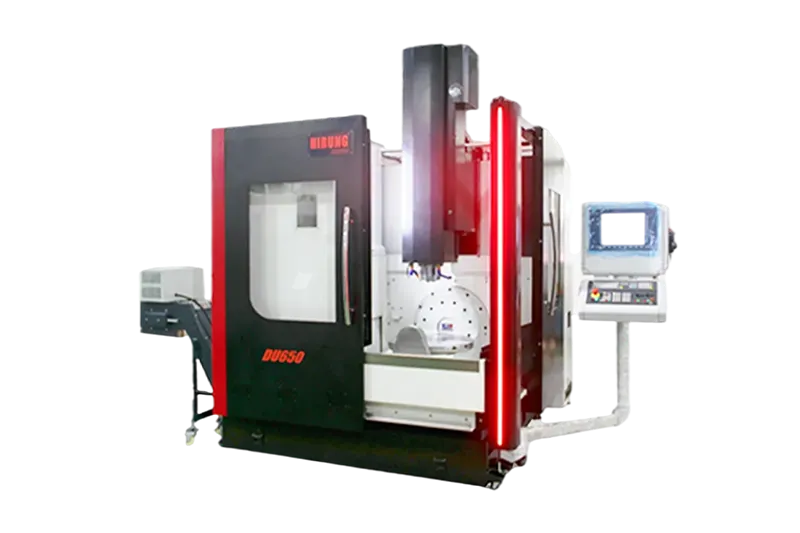
Accurate categorization simplifies the CAM workflow. However, machining complex part families — such as aerospace impellers or multi-sided brackets — requires reliable 5-axis machining centers that can maintain extreme rigidity and positional accuracy across all standardized toolpaths, because a template multiplies whatever accuracy or error the machine delivers: every part in the family inherits it.
Architecting Reusable CAM Operations
Once part families are established, the next step is building the master CAM templates. A CAM template is a saved sequence of machining operations containing predefined tool selections, cutting parameters, and linking movements.
To build effective and reusable CAM operations, follow this step-by-step process:
One design decision comes before any of the steps: template granularity. A template that is too narrow (locked to one part’s exact boundaries) gets bypassed by programmers in a hurry; one that is too broad (no default parameters at all) saves nothing. The practical sweet spot is a family-level master template with per-feature variants — one roughing module, one drilling module, one finishing module — that programmers enable or disable per part. Version it like software: a template change is a process change, and every part machined with the old version should be traceable to it.
Step 1: Standardize the Tool Library
Before saving any toolpaths, establish a locked tooling library for the specific part family. Define exact tool numbers, speeds, feeds, holder geometries, and stick-out lengths. If the CAM template assumes a specific shrink-fit holder but the operator uses a collet chuck, the programmed collision avoidance becomes invalid — the collision model is only as good as the holder architecture and reach assumptions behind it.
Step 2: Define Universal Roughing Strategies
Create roughing operations based on material type rather than specific part geometry. Save dynamic milling or high-efficiency roughing (HEM) strategies with established step-overs, step-downs, and safe stock-to-leave values. When applying the template to a new part, the programmer only needs to select the new solid model boundaries.
Step 3: Establish 5-Axis Finishing and Linking
For simultaneous 5-axis finishing, save templates that dictate specific lead and tilt angles, gouge-checking parameters, and retract behaviors. Standardize how the tool transitions between cuts (e.g., retracting to a safe clearance cylinder rather than a flat plane) to prevent unexpected tool wrap-arounds during multi-axis indexing. The method for selecting and validating those orientation angles by geometry is covered in our guide to lead and tilt control in simultaneous 5-axis machining.
Standardizing 5-Axis Setup Sheets to Prevent Collisions
Even the most optimized CAM template will fail if the setup information is not accurately communicated to the machine operator. 5-axis machining involves complex rotary movements where the spindle, tool holder, workholding, and machine trunnion operate in close proximity — a proximity governed largely by machine configuration, as the trunnion vs. swivel head rigidity and clearance comparison makes clear. A standardized setup sheet acts as the final defense against catastrophic collisions.
To align the CAM environment with the physical machine, every 5-axis setup sheet must include the following specifications:
- Work offset origin (G54–G59): exact physical location of the zero point (e.g., center of the rotary table, specific vise corner, or fixture dowel pin).
- Exact tool overhang limits: minimum required tool stick-out to clear the workpiece and maximum allowable stick-out to maintain rigidity.
- Blank material dimensions: precise stock size requirements to ensure the first roughing pass does not encounter unexpected heavy loads.
- A and C axis starting orientation: the required starting angles of the rotary table or spindle head before cycle start.
- Fixture clearance zones: identified areas where clamps, bolts, or vise jaws are located, requiring operator verification against the CAM simulation.
Treat the setup sheet as a living document tied to the template version: when the tool library changes, the overhang limits and clearance zones change with it. Shops that let the sheet drift out of sync with the CAM environment quietly rebuild the exact collision risk the template was designed to remove.
Transitioning Templates to Production: Realizing the ROI
Transitioning to template-driven programming fundamentally changes how a machine shop operates, in the same way the wider process and workflow changes of moving from 3-axis to 5-axis production reshuffle who does what on the floor. By removing repetitive data entry and manual toolpath creation, businesses can shift their engineering focus from basic programming to process optimization.
| Production Metric | Traditional Single-Part Programming | Template-Driven Part Family Workflow |
|---|---|---|
| CAM programming time | Hours or days per new component | Minutes (selecting boundaries and applying templates) |
| Collision risk | High (relies on programmer memory for clearances) | Low (clearances and retracts are hard-coded in the template) |
| Machine setup time | Extended (operators must verify new tools and unfamiliar setups) | Minimized (operators use standardized tools and familiar fixtures) |
| Spindle uptime | Low (machine waits for slow programming and cautious dry-runs) | High (programs are generated quickly and verified systematically) |
Templates also attack one of the quieter obstacles in 5-axis adoption — the CAM programming and collision-verification friction that slows teams down long after the machine is installed — which is where much of the real payback hides in 5-axis ROI calculations.
Do not forget the layer between the CAM system and the machine: the post-processor. Part families only standardize cleanly if every machine in the cell runs an identical, validated post (same kinematics, same rotary conventions, same output format). A template applied through a mismatched post silently rewrites safe retracts and orientation moves — which is why post validation belongs in the same review cycle as template versioning, not in a one-time setup task.
Next Steps for Your Machining Strategy
Standardizing your CAM workflow through part families and reusable operations eliminates the software bottleneck in your manufacturing process. However, optimized toolpaths demand machine tools capable of executing them flawlessly. Fast programming turnaround only translates to higher profitability if your equipment can handle continuous, rigorous production without deviation.
If you have optimized your programming but your current machines struggle with rigidity, volumetric accuracy, or surface finish during multi-axis interpolation, it is time to evaluate your hardware — start with the 5-axis machine specifications that actually separate good platforms from average ones. Explore HIRUNG’s 5-axis milling capabilities for complex geometries to find the ideal platform for your standardized part families, or consult with the HIRUNG technical team to discuss how our machine configurations align with your production requirements.
Key Takeaways
- Grouping components into part families allows engineers to apply master CAM templates to multiple distinct parts, drastically reducing programming time.
- Reusable CAM operations must rely on a standardized tool library with locked feeds, speeds, and exact holder geometries to remain safe and effective.
- 5-axis setup sheets must clearly define work offset origins, tool overhang limits, and starting rotary angles to prevent collisions between the CAM environment and the physical machine.
- Implementing CAM templates shifts engineering resources from repetitive data entry to process optimization, maximizing overall spindle uptime.
Frequently Asked Questions
What is a part family in CNC machining?
A part family is a group of components categorized by geometric similarities, material types, and tooling requirements. Grouping parts allows programmers to use standardized machining strategies and setups across multiple different workpieces.
Which 5-axis CAM operations are best suited for templates?
Heavy roughing strategies (like dynamic milling) and standard 3+2 positional indexing operations are highly effective as templates — deciding when to lock the rotary axes and run 3+2 instead of full 5-axis motion is itself a reusable decision per family. Simultaneous 5-axis surfacing operations can also be templated by locking in specific lead/tilt angles and gouge-checking rules.
How does a standardized setup sheet prevent 5-axis collisions?
A standardized setup sheet bridges the gap between the programmer’s virtual CAM environment and the operator’s physical machine. By strictly defining tool overhang lengths, fixture locations, and G-code zero points, it ensures the machine executes the toolpaths exactly as simulated, avoiding unexpected interference.