When machining deep cavities, tall walls, or complex aerospace components, tooling geometry often dictates cycle times. In a standard setup, reaching the bottom of a deep pocket requires a long cutting tool to prevent the spindle housing from colliding with the workpiece. However, extending tool overhang introduces severe mechanical disadvantages: rigidity drops, deflection spikes, and chatter destroys surface finishes.
The most effective mechanical solution to excessive tool overhang is not adjusting feeds and speeds, but altering the spatial approach angle. High-precision 5-axis machining allows operators to tilt the tool or the workpiece, physically maneuvering the spindle housing into the cavity and enabling the use of ultra-short, highly rigid cutting tools. This guide breaks down the physical impact of tool length, compares axis setups, and outlines best practices for maximizing rigidity.
The Hidden Costs of Excessive Tool Overhang in CNC Milling
Tool overhang — the distance from the tool holder face to the cutting edge — directly dictates the stiffness of the machining operation. In milling physics, a cutting tool acts as a cantilever beam: deflection under load is proportional to the cube of its unsupported length. This is the same cubic relationship that governs full tool assembly stiffness, and it is the single most important number in deep-cavity process planning.
This means that if you double the length of a cutting tool to reach a deep feature, the tool does not become twice as flexible; it becomes eight times more flexible. This exponential loss of rigidity triggers a cascade of production issues:
- Chatter and vibration: lack of stiffness causes the tool to bounce against the material, leaving visible chatter marks that require manual polishing or lead to part rejection. The interaction between overhang, machine configuration and damping is examined in detail in the trunnion vs. swivel head comparison of cutting rigidity, overhang and chatter control.
- Dimensional inaccuracy: as the tool deflects away from the cutting surface, it fails to remove the programmed amount of material, causing out-of-tolerance profiles. This is one of the main ways tool deflection and tool holding eat into achievable 5-axis tolerance capability.
- Premature tool failure: high vibration and uneven chip loads cause micro-chipping on the carbide cutting edges, drastically shortening tool life and increasing consumable costs.
The numbers make the case vividly. Take a 12 mm carbide end mill cutting a 60 mm deep pocket. At 25 mm of stick-out it flexes within tolerance and runs at full feed; extend the same cutter to 50 mm of stick-out to reach the floor and its deflection under identical radial load multiplies by roughly eight. The typical shop-floor response — dropping feed rate and depth of cut until the whistling stops — can easily double cycle time, and it still leaves the finish and tool-life penalties in place. Overhang is a geometry problem, and geometry problems need geometric answers.
How 5-Axis CNC Machining Solves the Short-Tool Dilemma
In traditional 3-axis machining, the tool remains strictly vertical (Z-axis). To machine a deep feature, the only collision-avoidance strategy is to extend the tool further out of the collet.
5-axis machines introduce two additional rotary axes (typically A and C, or B and C, depending on the trunnion or swivel-head configuration). By tilting the tool axis relative to the workpiece, the machine creates mechanical clearance. The spindle housing can drop deep into the machining envelope at an angle, safely clearing the vertical walls of the part. Choosing the right lead and tilt angles is exactly what converts this geometric freedom into usable clearance — and it is a skill covered end to end in our guide to tool orientation control in simultaneous 5-axis machining. This geometric advantage eliminates the need for long-reach tools.
Machine configuration determines how much of this clearance is actually available. Trunnion-style machines rotate the workpiece under a stationary spindle and usually deliver a generous rotary range (commonly ±110° or more on the A-axis), which is ideal for reaching around tall walls. Swivel-head machines tilt the spindle itself, so the head’s clearance profile — its nose diameter and pivot-to-gauge distance — becomes part of the collision equation. Either way, the rule is the same: every degree of tilt that moves the spindle nose away from the wall is a degree of overhang you no longer need to buy back with a longer, floppier cutter.
| Feature | 3-Axis Setup | 5-Axis Setup |
|---|---|---|
| Tool approach | Vertical only (Z-axis restricted) | Angled (utilizing rotary/tilt axes) |
| Collision avoidance | Requires extended tool overhang | Spindle housing tilts to clear part walls |
| Tool rigidity | Low (susceptible to heavy deflection) | High (supports short, stubby tools) |
| Cutting parameters | Reduced feeds and depths to prevent chatter | Aggressive feeds and depths permitted |
| Part setup | May require multiple setups for deep draft angles | Single setup finishes deep and undercut features |
Measurable Benefits of Using Shorter Tools in 5-Axis Setups
Upgrading a process to utilize shorter tools through 5-axis articulation yields immediate, quantifiable improvements on the shop floor:
- Exponentially higher rigidity: keeping the length-to-diameter (L/D) ratio as low as possible maximizes the tool’s structural integrity, allowing the carbide to cut cleanly rather than bending under radial load. The workflow for verifying L/D ratios and adjusting cutting parameters step by step is laid out in our 5-axis tool assembly planning guide.
- Elimination of chatter: short tools possess higher natural frequencies, making them far less prone to resonant vibration during heavy roughing or cornering. This directly translates to superior surface finishes — and where the material itself is difficult, dedicated damping strategies stabilize hard-material cutting even further.
- Faster material removal rates (MRR): with deflection neutralized, programmers can push feed rates, spindle speeds and step-downs closer to the tool manufacturer’s maximum specifications without fear of breakage.
- Extended tool life: stable cutting conditions distribute the thermal and mechanical load evenly across the flutes. This prevents premature edge chipping, reducing the frequency of tool changes and lowering overall carbide costs.
Best Practices for Tooling and Setup in 5-Axis Machining
While 5-axis kinematics allow for shorter tools, the physical setup must be equally rigid to capitalize on this advantage.
1. Optimize Tool Holder Selection
A short tool in a poor holder negates the rigidity benefits. Avoid standard ER collets for heavy 5-axis roughing. Instead, utilize shrink-fit or hydraulic tool holders — the trade-offs between shrink-fit, hydraulic and collet chuck assemblies are compared directly in our tool holder architecture guide. These holders offer superior gripping force, smaller nose profiles (providing even more clearance), and minimal runout, ensuring the short tool rotates perfectly true. The machine-side half of the decision matters too: confirm which taper interface standard (HSK vs. BT and dual-contact designs) your spindle supports before standardizing on a holder system.
2. Elevate the Workpiece
To fully utilize the tilt capabilities of a 5-axis trunnion without causing interference between the machine table and the spindle, the workpiece must be elevated. Use zero-point clamping systems, dovetail fixtures, or pyramid risers. This lifts the raw block away from the table surface, giving the spindle unrestricted 5-axis access to the bottom edges of the part — a practical extension of the workholding and tooling rethink that comes with moving from 3-axis to 5-axis production. Size the riser for the worst-case rotation, not the nominal setup: the block should clear the table through the full tilt range of the trunnion, including the extreme positions where the part swings closest to the machine table. A fixture that works at 0° and crashes at 90° defeats the entire short-tool strategy.
3. Mandate CAM Collision Simulation
Because 5-axis machining with short tools brings the bulky spindle casting dangerously close to the workpiece and fixtures, digital verification is non-negotiable. Programmers must run exact machine kinematics and precise tool holder models through CAM collision simulation to verify that the shortened overhang leaves adequate clearance throughout the entire toolpath. The five-step workflow that culminates in a full kinematic machine simulation belongs in every deep-cavity job plan, and it pairs naturally with the deep mold cavity tilt and collision-control strategies used on the CAM side.
Key Takeaways
- Tool deflection increases exponentially with length; doubling tool length makes it eight times more flexible.
- 5-axis machining uses tilt and rotary axes to provide spindle clearance, allowing the use of ultra-short, highly rigid tools in deep cavities.
- Shorter tools directly improve surface finish, extend tool life, and allow for maximum material removal rates (MRR).
- To maximize these benefits, pair short tools with shrink-fit holders, elevated zero-point workholding, and strict CAM simulation.
Frequently Asked Questions
What is the ideal length-to-diameter (L/D) ratio for CNC tools?
For maximum rigidity, aim for an L/D ratio of 3:1 or lower. Ratios exceeding 5:1 begin to introduce noticeable deflection, requiring lighter cuts. 5-axis machining excels at keeping operations within the optimal 3:1 threshold — the cubic law behind this limit is derived in our guide to gauge length, reach and rigidity.
Can 3+2 positional machining also reduce tool overhang?
Yes. In 3+2 machining, the rotary axes tilt the part to a fixed angle and lock in place before a standard 3-axis toolpath runs. This still provides the clearance needed to use short tools, even if all 5 axes are not moving simultaneously. The rigidity-versus-flexibility trade-off between simultaneous 5-axis and 3+2 machining explains when locking the axes is the better process choice.
Does reducing tool length completely eliminate chatter?
While minimizing overhang is the most critical factor in fighting chatter, it is not the only variable. Spindle condition, tool holder runout, fixture stability, and properly calculated chip loads must also be optimized — which is why high-precision tool interfaces for reduced vibration remain a first-line investment even on short-tool jobs.
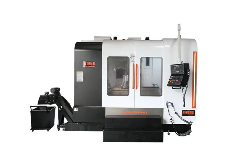
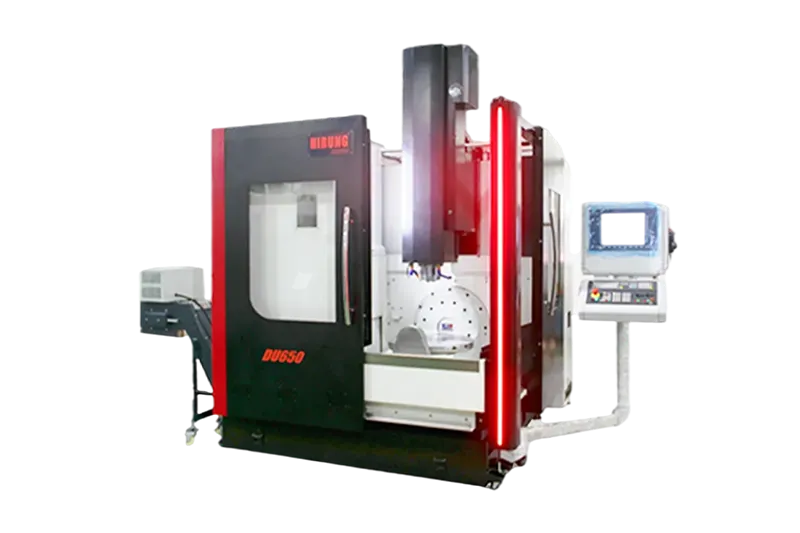
Maximize Your Machining Efficiency with HIRUNG 5-Axis Solutions
Overcoming tool deflection and extending carbide life requires more than just high-quality tooling; it demands machine kinematics capable of superior spatial positioning. By utilizing 5-axis technology to angle the spindle and reduce tool overhang, manufacturers can drastically increase material removal rates while holding tighter tolerances on complex features.
Transitioning from tool-limited 3-axis processes to clearance-optimized 5-axis setups is a critical step in modernizing part production. Explore HIRUNG’s 5-axis milling capabilities for complex geometries, then send the geometry to the HIRUNG engineering team for a manufacturability review — we will confirm whether your deep-cavity features can run on short, rigid tooling from the first quote.